Nikola Tesla Books
the table of 13,474 cm. This, with the 41,000 cm as before, would give an approximate inductance of 54,500 cm for the exciting circuit and from this
Tp = !$ {{2 \pi \over 10^{3}} \sqrt{0.0099 \times {545 \over 10^{7}}}} !$ = !$ {{2 \pi \over 10^{6}} \sqrt{0.00099 \times 545}} !$ =
= !$ {{2 \pi \over 10^{6}} \sqrt{0.53955}} !$ = !$ {{2 \pi \over 10^{6}} \times 0.735} !$ = !$ {4.6158 \over 10^{6}} !$
and n = 217,000 per sec. approx.
As in this case the capacity may be put approximately at 500 cm, we may roughly estimate the effective inductance in the excited circuit. Namely, calling this inductance Ls we have, for the condition of resonance,
Tp = Ts or !$ {{2 \pi \over 10^{3}} \sqrt{0.0099 \times {545 \over 10^{7}}}} !$ = !$ {{2 \pi \over 10^{3}} \sqrt{{500 \over {9 \times 10^{5}}} L_{s}}} !$
and from this
Ls = !$ {{0.0099 \times 545 \times 9} \over {5 \times 10^{4}}} !$ = !$ {48.56 \over {5 \times 10^{4}}} !$ henry
or
!$ {{48.56 \times 10^{5}} \over 5} !$ = !$ {4,856,000 \over 5} !$ = 971,200 cm.
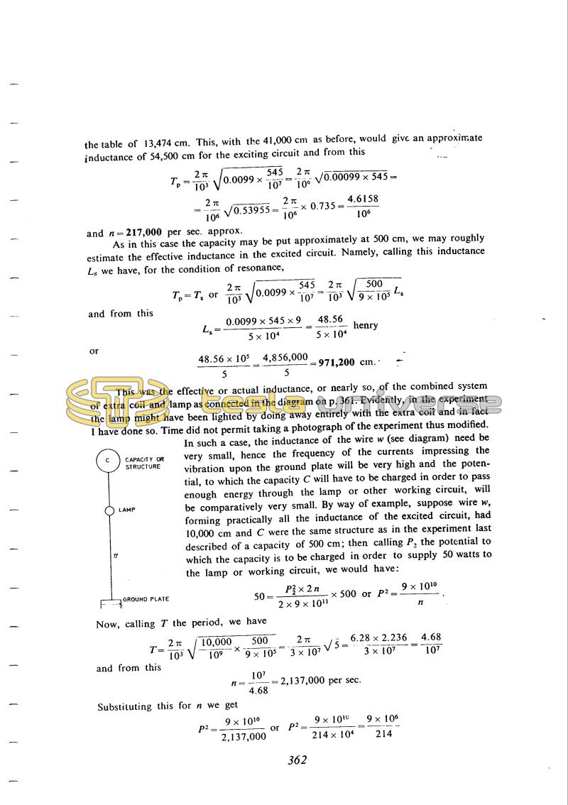
This was the effective or actual inductance, or nearly so, of the combined system of extra coil and lamp as connected in the diagram on p. 361. Evidently, in the experiment the lamp might have been lighted by doing away entirely with the extra coil and in fact I have done so. Time did not permit taking a photograph of the experiment thus modified.
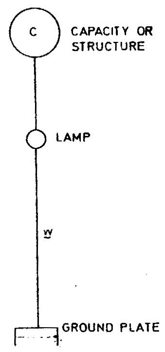
In such a case, the inductance of the wire w (see diagram) need be very small, hence the frequency of the currents impressing the vibration upon the ground plate will be very high and the potential, to which the capacity C will have to be charged in order to pass enough energy through the lamp or other working circuit, will be comparatively very small. By way of example, suppose wire w, forming practically all the inductance of the excited circuit, had 10,000 cm and C were the same structure as in the experiment last described of a capacity of 500 cm; then calling P2 the potential to which the capacity is to be charged in order to supply 50 watts to the lamp or working circuit, we would have:
50 = !$ {{{P^{2}}_{2} \times 2 n} \over {2 \times 9 \times 10^{11}}} !$ x 500 or P2 = !$ {9 \times 10^{10} \over n} !$.
Now, calling T the period, we have
T = !$ {{2 \pi \over 10^{3}} \sqrt{{10,000 \over 10^{9}} \times {50 \over {9 \times 10^{5}}}}} !$ = !$ {{2 \pi \over {3 \times 10^{7}}} \sqrt{5}} !$ = !$ {{6.28 \times 2.236} \over {3 \times 10^{7}}} !$ = !$ {4.68 \over 10^{7}} !$
and from this
n = !$ {10^{7} \over 4.68} !$ = 2,137,000 per sec.
Substituting this for n we get
P2 = !$ {{9 \times 10^{10}} \over 2,137,000} !$ or P2 = !$ {{9 \times 10^{10}} \over {214 \times 10^{4}}} !$ = !$ {{9 \times 10^{6}} \over 214} !$
362
The explanation to Photograph XXII concerning the transmission of power from the excited primary circuit to the "extra coil" via the earth is similar to that he gave in 1893(6). The experiment to which the photograph refers was made with the aim of estimating the power of the oscillator from the thermal effect of the HF current. What Tesla calls the "total energy set in movement" would correspond to the total energy transferred to condenser in the secondary (i.e. the power) if an energy of !${1 \over 2}!$ CV2 is transferred in each half-cycle. It can be shown that the active power dissipated in the circuit is much less than this and is inversely proportional to the Q-factor of the oscillating circuit.
January 2
Tesla gave his observations on 22 pages. On them he described eleven photographs. The explanation along with photograph No. 22 about energy transmission from excitation of the primary circuit to "additional coil" over the earth surface is similar to the one from 1893(6). Otherwise the experiment to which the photograph is related was performed for the purpose of oscillator power estimate on the basis of thermal effects of high frequency current.
That which Tesla calls "total energy placed in motion" would correspond to the total energy which is supplied to a capacitor per second (i.e. power) if energy ½CV2 is supplied during the duration of one half of the period.
It could be shown that the active power which is spent in the circuit is considerably smaller than this power, and opposite, proportionally to the quality factor of the oscillating circuit. On several following photographs, the movable resonant coil with connected bulbs is photographed which is supplied by transmitted high frequency energy. One terminal of this coil is connected to the ground, and the other is open ended or a short piece of wire is connected to it. Bulbs are coupled by means of the auxiliary secondary coil inductively with the secondary coil. The data was not given on the distance of resonant coil from the oscillator coil. Tesla's comment on photograph No. 27 illustrates the interest on the question of electrical lightning, though he worked on this for more than ten years. One earlier discovery on gas elimination and not only filament, when working with high frequency currents is again proven(5).
On photograph No. 28 the bulb is connected in series with a terminal capacitance load. In the calculations "total energy placed in movement" is not taken when it was assumed that the electrostatic energy ½CV2 is spent in the bulb during one half of the period. A similar comment is valid for photograph No. 29.
Tesla mentioned several times that the main transmission from the exciting to the excited circuit is done via the ground. The proof for this statement he found in the experiment illustrated by photograph No. 30. He concluded that the induced voltage in the excited circuit is significantly reduced when the ground connection is disconnected. Photograph No. 31 is an X-ray photograph of a finger. The comments on this experiment are an illustration of Tesla's interest in the radiation field which was mentioned earlier (please see comment on June 6, 1899).


