Nikola Tesla Books
Colorado Springs
July 2, 1899
Considerations regarding best conditions of working apparatus in experimental station particularly with reference to stationary waves in the ground which will be investigated.
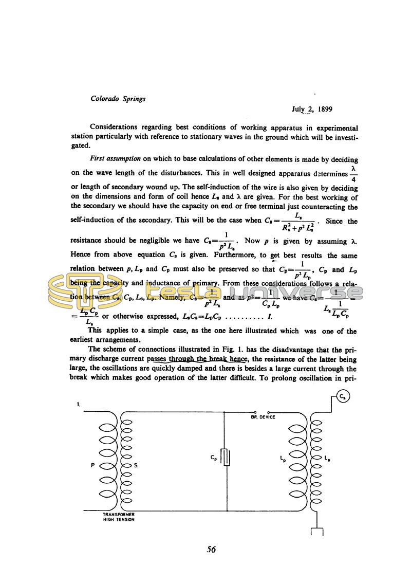
First assumption on which to base calculations of other elements is made by deciding on the wave length of the disturbances. This in well designed apparatus determines !$ {λ \over 4} !$ or length of secondary wound up. The self-induction of the wire is also given by deciding on the dimensions and form of coil hence Ls and λ are given. For the best working of the secondary we should have the capacity on end or free terminal just counteracting the self-induction of the secondary. This will be the case when Cs = !$ {L_{s} \over {R_{s}^{2} + p^{2} L_{s}^{2}}} !$. Since the resistance should be negligible we have Cs = !$ {1 \over {p^{2} L_{s}}} !$. Now p is given by assuming λ. Hence from above equation Cs is given. Furthermore, to get best results the same relation between p, Lp and Cp must also be preserved so that Cp = !$ {1 \over {p^{2} L_{p}}} !$, Cp and Lp being the capacity and inductance of primary. From these considerations follows a relation between Cs, Cp, Ls, Lp. Namely, Cs = !$ {1 \over {p^{2} L_{s}}} !$ and as p2 = !$ {1 \over C_{p} L_{p}} !$ we have Cs = !$ {1 \over {L_{s} {1 \over {L_{p} C_{p}}}}} !$ = !$ {L_{p} C_{p} \over L_{s}} !$ or otherwise expressed, LsCs = LpCp . . . . . . . . . . I.
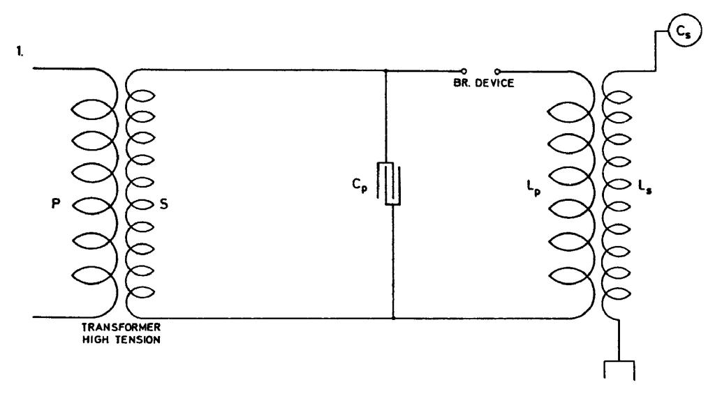
This applies to a simple case, as the one here illustrated which was one of the earliest arrangements.
The scheme of connections illustrated in Fig. 1. has the disadvantage that the primary discharge current passes through the break hence, the resistance of the latter being large, the oscillations are quickly damped and there is besides a large current through the break which makes good operation of the latter difficult. To prolong oscillation in pri-
56
July 2
Here Tesla gives the calculation of values for the spark gap oscillator in the fullest detail so far. However, the analysis does not include all the magnitudes relevant to the functioning of the oscillator, e.g. the primary/secondary coupling of the transformer and the distributed capacitance of the secondary. The power equation is also not fully explained and justified. However, by means of this approximate calculation Tesla did get a valuable rough guide relatively quickly and easily.
July 2
From that which has so far been given in segments, he finally formulates completely as a method as to how to perform the approximate calculation on the oscillator in Figure No. 1. For the purpose of clarity we will repeat Tesla's calculation method:
- the designed oscillator wavelength is chosen;
- on the basis of wavelength the secondary coil wire length is determined as one quarter of the wavelength;
- secondary inductance is determined on the basis of known wire length and chosen coil shape;
- for most efficient operation the capacitance at the open secondary terminal has to be such that Cs= 1/p2Ls, by neglecting the losses;
- the inductance and capacitance of oscillator primary circuit are determined on the basis that the condition of equal own primary and secondary frequencies is met: LpCp = LsCs. Normally Lp is much smaller than Ls so that the winding ratio of primary and secondary Np/Ns is much smaller than 1.
In procedure we have shown, there is no mention about mutual link between primary and secondary. Secondary distributed capacitance is neglected as well. With the oscillator shown in Figure No. 2, the arcing device is outside of primary circuit LpCp and this according to Tesla enables the achievement of less dampened oscillations in the primary circuit and less current through the arcing device. Under assumption that at the operation frequency circuit LpCp is in resonance, the current 'i' is considerably smaller than current i2. Capacitance C1 (which appears in Figures 3 and 4 as
well) is determined so that it can accumulate the entire energy which can be transmitted from the network via the supply transformer. At discharge of C1 accumulated energy is converted to energy of high frequency currents. Additional condition for C1 is given by equation II.


