Nikola Tesla Books
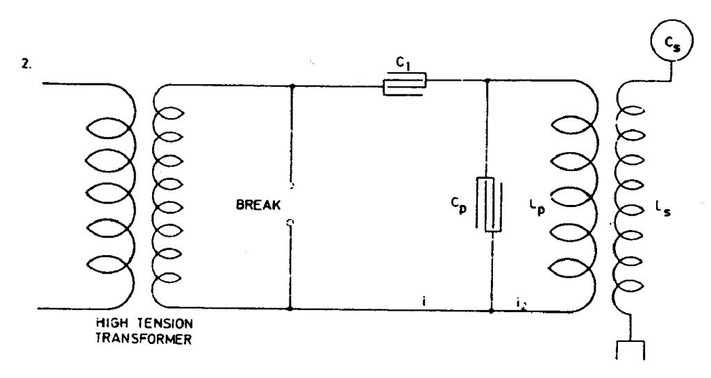
mary and increase economy one of the schemes before considered may be resorted to. One of these is illustrated in Fig. 2. which follows: in this arrangement the currents through the break device are much smaller and the oscillations started by the operation of break
in circuit LpCp continue much longer. We can now determine the magnitude of currents i, i2. Capacity Cp = !$ {L_{p} \over {R_{p}^{2} + p^{2} L_{p}^{2}}} !$ from foregoing or approximately Cp = !$ {1 \over {p^{2} L_{p}}} !$ as before, neglecting resistance. We have then !$ {{i_{2} \over i} = {\sqrt{R_{p}^{2} + p^{2} L_{p}^{2} \over R_{p}^{2}}} } !$ or, since the first term is negligible in numerator, we have !$ {{i_{2} \over i} = {p L_{p} \over R_{p}}} !$ or i2 = !$ {i {pL_{p} \over R_{p}}} !$. From this relation it is evident that, other difficulties or disadvantages not considering the arrangement as illustrated in Fig. 2. should be superior to that in Fig. 1. It secures two chief advantages: 1) less current through the break and more through the primary and 2) longer and better oscillation in circuit including primary because it is easy to constitute such a system without break with an extremely small resistance or frictional waste.
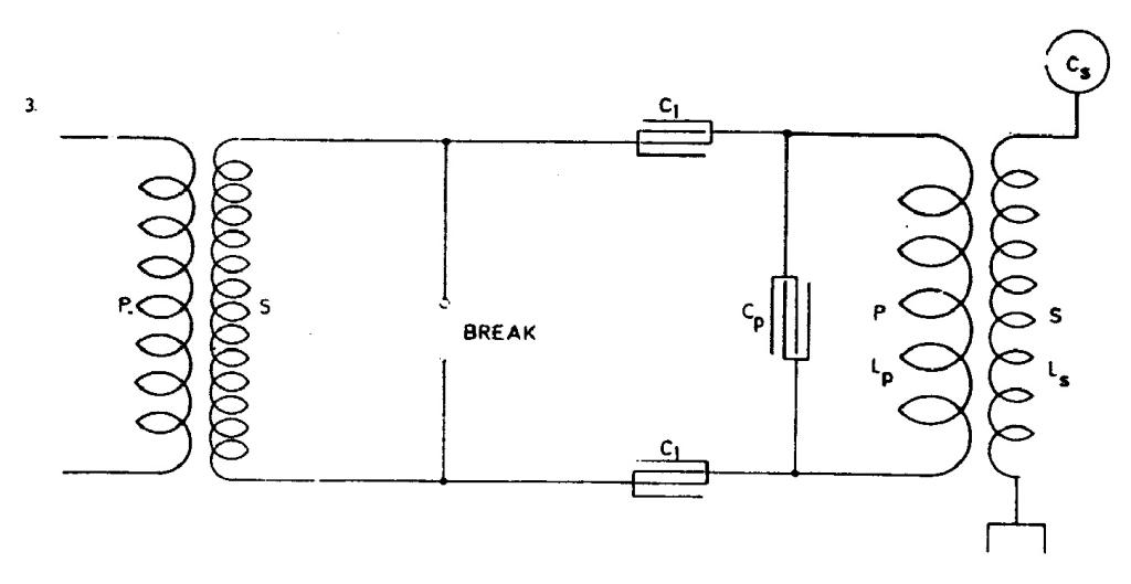
Fig. 3. illustrates an arrangement similar to that shown in Fig. 2. but with a condenser in each branch. The same considerations made in regard to Fig. 2. hold good for this and in both cases, if there is to be resonance and best conditions attained, the circuit including the break should have the same period and be in phase with primary circuit LpCp and secondary LsCs. Referring to Fig. 2. as the simpler, this is the case when the
57
July 2
Here Tesla gives the calculation of values for the spark gap oscillator in the fullest detail so far. However, the analysis does not include all the magnitudes relevant to the functioning of the oscillator, e.g. the primary/secondary coupling of the transformer and the distributed capacitance of the secondary. The power equation is also not fully explained and justified. However, by means of this approximate calculation Tesla did get a valuable rough guide relatively quickly and easily.
July 2
From that which has so far been given in segments, he finally formulates completely as a method as to how to perform the approximate calculation on the oscillator in Figure No. 1. For the purpose of clarity we will repeat Tesla's calculation method:
- the designed oscillator wavelength is chosen;
- on the basis of wavelength the secondary coil wire length is determined as one quarter of the wavelength;
- secondary inductance is determined on the basis of known wire length and chosen coil shape;
- for most efficient operation the capacitance at the open secondary terminal has to be such that Cs= 1/p2Ls, by neglecting the losses;
- the inductance and capacitance of oscillator primary circuit are determined on the basis that the condition of equal own primary and secondary frequencies is met: LpCp = LsCs. Normally Lp is much smaller than Ls so that the winding ratio of primary and secondary Np/Ns is much smaller than 1.
In procedure we have shown, there is no mention about mutual link between primary and secondary. Secondary distributed capacitance is neglected as well. With the oscillator shown in Figure No. 2, the arcing device is outside of primary circuit LpCp and this according to Tesla enables the achievement of less dampened oscillations in the primary circuit and less current through the arcing device. Under assumption that at the operation frequency circuit LpCp is in resonance, the current 'i' is considerably smaller than current i2. Capacitance C1 (which appears in Figures 3 and 4 as
well) is determined so that it can accumulate the entire energy which can be transmitted from the network via the supply transformer. At discharge of C1 accumulated energy is converted to energy of high frequency currents. Additional condition for C1 is given by equation II.


