Nikola Tesla Books
relation between C1 and self-induction in this circuit is such that they annul each other at that frequency.
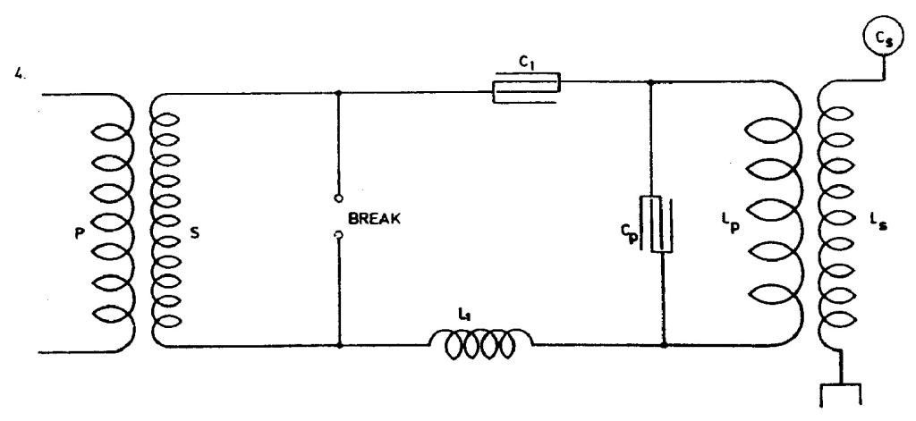
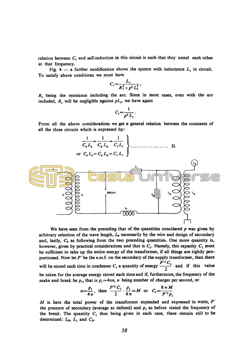
Fig. 4 - a further modification shows the system with inductance L1 in circuit. To satisfy above conditions we must have
C1 = !$ {L_{1} \over {R_{1}^{2} + p^{2} L_{1}^{2}}} !$ ,
R1 being the resistance including the arc. Since in most cases, even with the arc included, R1 will be negligible against pL1, we have again
C1 = !$ {1 \over {p^{2} L_{1}}} !$.
From all the above considerations we get a general relation between the constants of all the three circuits which is expressed by:
!$ {{1 \over {C_{s} L_{s}}} = {1 \over {C_{p} L_{p}}} = {1 \over {C_{1} L_{1}}}} !$ or CsLs = CpLp = C1L1 . . . . . . . . . . II.
We have seen from the preceding that of the quantities considered p was given by arbitrary selection of the wave length, Ls necessarily by the wire and design of secondary and, lastly, Cs as following from the two preceding quantities. One more quantity is, however, given by practical considerations and that is C1. Namely, this capacity C1 must be sufficient to take up the entire energy of the transformer, if all things are rightly proportioned. Now let P' be the e.m.f. on the secondary of the supply transformer, then there will be stored each time in condenser C1 a quantity of energy !$ {P'^{2} C_{1} \over 2} !$ and if this value be taken for the average energy stored each time and if, furthermore, the frequency of the make and break be p1, that is p1 = 4â¼n, n being number of charges per second, or
n = !$ {p_{1} \over 4 \pi} !$, then !$ {P'^{2} C_{1} \over 2} !$. !$ {p_{1} \over 4 \pi} !$ = M or C1 = !$ {{8 \pi M} \over {P'^{2} p_{1}}} !$
M is here the total power of the transformer expended and expressed in watts, P' the pressure of secondary (average as defined) and p1 as before stated the frequency of the break. The quantity C1 thus being given in each case, these remain still to be determined: Lp, L1 and Cp.
58
July 2
Here Tesla gives the calculation of values for the spark gap oscillator in the fullest detail so far. However, the analysis does not include all the magnitudes relevant to the functioning of the oscillator, e.g. the primary/secondary coupling of the transformer and the distributed capacitance of the secondary. The power equation is also not fully explained and justified. However, by means of this approximate calculation Tesla did get a valuable rough guide relatively quickly and easily.
July 2
From that which has so far been given in segments, he finally formulates completely as a method as to how to perform the approximate calculation on the oscillator in Figure No. 1. For the purpose of clarity we will repeat Tesla's calculation method:
- the designed oscillator wavelength is chosen;
- on the basis of wavelength the secondary coil wire length is determined as one quarter of the wavelength;
- secondary inductance is determined on the basis of known wire length and chosen coil shape;
- for most efficient operation the capacitance at the open secondary terminal has to be such that Cs= 1/p2Ls, by neglecting the losses;
- the inductance and capacitance of oscillator primary circuit are determined on the basis that the condition of equal own primary and secondary frequencies is met: LpCp = LsCs. Normally Lp is much smaller than Ls so that the winding ratio of primary and secondary Np/Ns is much smaller than 1.
In procedure we have shown, there is no mention about mutual link between primary and secondary. Secondary distributed capacitance is neglected as well. With the oscillator shown in Figure No. 2, the arcing device is outside of primary circuit LpCp and this according to Tesla enables the achievement of less dampened oscillations in the primary circuit and less current through the arcing device. Under assumption that at the operation frequency circuit LpCp is in resonance, the current 'i' is considerably smaller than current i2. Capacitance C1 (which appears in Figures 3 and 4 as
well) is determined so that it can accumulate the entire energy which can be transmitted from the network via the supply transformer. At discharge of C1 accumulated energy is converted to energy of high frequency currents. Additional condition for C1 is given by equation II.


