Various Tesla book cover images

Nikola Tesla Books

Books written by or about Nikola Tesla

Related content from pages

Designation
353

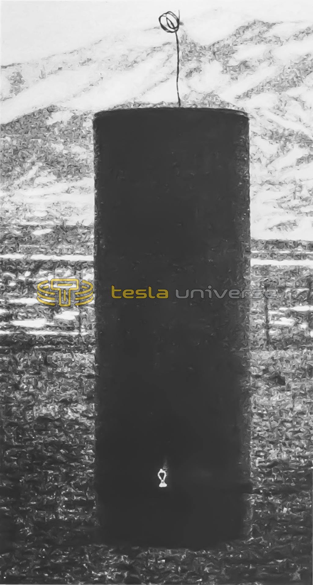
One more experiment of this kind was photographed, the same coil being again used and placed far out into the field, this being shown in Plate XXVI., giving a clear view of the Pike's Peak Mountain Range in the background. The diagrams and several remarks before made apply to some extent also to these three photographs which were taken after sunset when the dark began to set in, as it was impracticable to take them at another hour of the day. They might have been taken by moonlight but the time was otherwise occupied. During the hours when the light was strong it would have been necessary to exclude first the daylight in some way, flash the lamp in the dark and finally make a short exposure to the full daylight to get the detail of the apparatus. It was found impracticable to get a good photograph by flashing the lamp in full daylight as the latter was too strong and the lamp did not have enough time to impress the plate as strongly as was desirable, even if it was pushed to much higher candle power than the normal. In getting the photographs, generally about 100 throws of the switch were sufficient with the lamp being pushed considerably above the normal. When the daylight was still deemed too strong Mr. Alley helped himself by covering the lens during the short interval when the lamp was not lighted and thus regulated the effect of the daylight, keeping it down to the required value.

The particulars were as follows: The coil used in these three experiments was wound on a drum before referred to of 25.25" diam. and had 274 turns of wire No. 10, rubber covered. Since another coil wound on the same drum had 404 turns and an inductance of approximately 40,000,000 cm. or 0.04 henry the inductance of the present coil was with fair approximation $! {\left({274 \over 404}\right)^{2}} $! x 0.04 henry or $! {\left({137 \over 202}\right)^{2}} $! x 0.04 henry. The wire leading from the ground plate to the lower end of the coil placed on the table or ground consisted of two pieces of cord No. 10, one 308 feet and the other 84 feet long. The inductance of these two pieces of wire was estimated at 113,000 cm and compared with the inductance of the coil itself was very small, almost negligible. Calling the total inductance of the excited circuit comprising the two pieces of wire and the coil used L1 we have for this inductance value L1 = $! {\left({137 \over 202}\right)^{2}} $! x 40,000,000 + 113,000 = 18,400,000 + 113,000 = 18,513,000 cm, or L1 = $! {185 \over 10^{4}} $! henry. This inductance, with its distributed capacity, gave a system responding

Designation
355

to the primary vibration when the capacity in the primary or exciting circuit was 1 2/3 tanks or 60 bottles on each side, or 30 bottles total, that is, 30 x 0.0009 = 0.027 mfd, total.

The vibrations were impressed on the ground plate by the oscillator with normal connection, that is, two primary cables in multiple or one primary turn, the approximate inductance of which was 56,400 cm or, say, 56,000 cm, which is close enough for the present consideration. This inductance may have been modified by the secondary, but the effect of the latter must have been very slight as, with the capacity used, it was “out of tune” and the current through it was necessarily very small. Taking then the inductance of the primary exciting circuit at 56,000 cm, the period of this circuit was

Tp = $! {{2 \pi \over 10^{3}} \sqrt{0.027 \times {56 \over 10^{6}}}} $!.

Now calling Cs the “ideal” capacity of the excited circuit, the period of the same was

Ts = $! {{2 \pi \over 10^{3}} \sqrt{{185 \over 10^{4}} \times C_{s}}} $! and equating we have Cs = $! {{10^{4} \over 185} \times 0.027 \times {56 \over 10^{6}}} $! = $! {{56 \times 0.027} \over {185 \times 10^{2}}} $! mfd,

or Cs = $! {{9 \times 10^{5} \times 56 \times 0.027} \over {185 \times 10^{2}}} $! = $! {{243 \times 56} \over 185} $! = 75.2 cm, approx. From above

Tp = $! {{2 \pi 10^{3}} \sqrt{0.027 \times {56 \over 10^{6}}}} $! = $! {{2 \pi \over 10^{3}} \sqrt{1.512}} $! = $! {{6.28 \over 10^{6}} \times 1.23} $! = $! {7.7244 \over 10^{6}} $!

and n = 129,500 per second nearly.

The theoretical wave length would thus be λ = $! {186,000 \over 130,000} $! = $! {186 \over 130} $! = 1.43 miles approx.

or $! {λ \over 4} $! = $! {1.43 \over 4} $! = 0.3575 miles or 0.3575 x 5280 = 1888 feet = $! {λ \over 4} $!.

The actual length of wire in the experiment was: 274 turns of the coil, each 79.29" = 1810 feet + one piece of wire 304 feet + one piece of wire 84 feet = 1810 + 304 + 84 = 2198 feet or nearly 15% more than the theoretical value. The fact is, the adjustment for resonance was not quite close as the lamp lighted could not withstand the current by closer adjustment. Two of these lamps were broken. The energy transmitted through the ground to the coil was, of course, small in this instance, since only a small part of the available primary capacity was used, that is, $! {1.66 \over 8} $! of the available capacity and the current of the supply transformers was reduced as far as practicable. If a coil especially adapted for the full output of the oscillator would have been used it would have been practicable to transmit many times the amount of energy needed for lighting the lamp. The lamps used in this experiment were special ones each taking, under the conditions of the experiment, perhaps 10 watts or nearly so. Assuming again a circuit under ideal conditions with the capacity of 75.2 cm on the free end of a coil without distributed capacity, and calling the potential to which this capacity would be charged P, the total energy set

Designation
356

in movement in the excited system would be 2 x 129,500 x $! {{P^{2} \times 75.2} \over {2 \times 9 \times 10^{11}}} $! watts.

If we assume that, as before, 1% of the total energy of the system is frittered down in the lamp we would have, in conformity with what was stated before for determining P, the equation

$! {2 \times 129,500 \times {{P^{2} \times 75.2} \over {2 \times 9 \times 10^{11}}}} $! = 1000 or P2 = $! {{18 \times 10^{11}} \over 259} $!

or

P = $! {10^{5} \sqrt{180 \over 259}} $! = $! {10^{5} \sqrt{0.695}} $! = $! {10^{5} \times 0.834} $!

or 83,400 V nearly, which is a small e.m.f. The length of wire in excited circuit was as before stated 2198 feet; the wire being No. 10, with a resistance of 1 ohm per one thousand feet, the resistance of the circuit was about 2.2 ohm. From above p = 2πn was = 6.28 x 129,500 = 813,260 or, say, 813,000 = p. The inductance being, as shown, $! {185 \over 10^{4}} $! henry, the magnifying factor in the coil was $! {{{185 \over 10^{4}} \times 813 \times 10^{3}} \over 2.2} $! = 6840 nearly. The lamp was one with a very short filament and its resistance may have been possibly 6 ohms. Thus with the lamp comprised the magnifying factor was still very considerable, that is, $! {{185 \times 813} \over 82} $! = 1830 or nearly so. Taking it at 1800 we see that it was necessary, under the conditions assumed, to impress upon the ground plate, or near portions of the ground an electromotive force of only $! {83,400 \over 1800} $! = $! {834 \over 18} $! = 52 volts or nearly so! This seems very little indeed, it can be scarcely believed, but the figures seem to be not far from truth. These remarks refer particularly to the experiment illustrated on the plate marked XXIV. in which the connections were the same as in the diagram shown when discussing Plate XXII., the lamp or lamps being in series with the excited coil or system.

Related content from annotations

January 1

Photograph XVII shows lamps connected into a resonant circuit consisting of one square turn. According to the data Tesla gives, one side of the square was about 1.3 m from the secondary coil of the oscillator. The capacity of the oscillatory circuit consisted of two condensers in parallel. The lamps are paralleled.

Tesla calculates the inductance of the square turn from the formula for the inductance of two parallel conductors, as if there were two such pairs connected in series. The formula for a square coil (Fleming, p. 155),

L = 8l(In $!{d \over r}$! - 0.774)

yields a value 12.6% less than Tesla found. The calculated resonant frequency is therefore somewhat higher than it should be, so that the inductance of the oscillator primary, as Tesla calculates it, is still less. In fact, because of the tight coupling of the secondary the oscillator must have been producing a complex spectrum, probably with its strongest component at the resonant frequency of the oscillatory circuit of the square coil.

In connection with photographs XVIII - XXI showing the secondary producing intense discharges, Tesla makes an interesting remark about signalling over great distances. Comparing this with other induction apparatuses he had constructed, he concludes that one could expect signals to be picked up at distances of a thousand miles or more, even on the Earth's surface. The diary does not mention any measurements at great distances, but in an article(41) he published soon after finishing work at Colorado Springs he states that he observed effects at a distance of about 600 miles.

23

Hertz, H.R. UNTERSUCHUNGEN UBER DIE AUSBREITUNG DER ELEKTRISCHEN KRAFT, dritte auflage, Leipzig, 1914, Johann Ambrosius Barth.

Phot. XXVI. Experiment to illustrate the transmission of electrical energy without wire. The photograph shown is reproduced from Tesla's article *.

Glossary

Lowercase tau - an irrational constant defined as the ratio of the circumference of a circle to its radius, equal to the radian measure of a full turn; approximately 6.283185307 (equal to 2π, or twice the value of π).
A natural rubber material obtained from Palaquium trees, native to South-east Asia. Gutta-percha made possible practical submarine telegraph cables because it was both waterproof and resistant to seawater as well as being thermoplastic. Gutta-percha's use as an electrical insulator was first suggested by Michael Faraday.
The Habirshaw Electric Cable Company, founded in 1886 by William M. Habirshaw in New York City, New York.
The Brown & Sharpe (B & S) Gauge, also known as the American Wire Gauge (AWG), is the American standard for making/ordering metal sheet and wire sizes.
A traditional general-purpose dry cell battery. Invented by the French engineer Georges Leclanché in 1866.
Refers to Manitou Springs, a small town just six miles west of Colorado Springs, and during Tesla's time there, producer of world-renown bottled water from its natural springs.
A French mineral water bottler.
Lowercase delta letter - used to denote: A change in the value of a variable in calculus. A functional derivative in functional calculus. An auxiliary function in calculus, used to rigorously define the limit or continuity of a given function.
America's oldest existing independent manufacturer of wire and cable, founded in 1878.
Lowercase lambda letter which, in physics and engineering, normally represents wavelength.
The lowercase omega letter, which represents angular velocity in physics.