
TCBA Volume 18 - Issue 1
Page 16 of 18
Experimenting with the Bottle Oudin
The illustration in Fig. 3 shows us several very interesting and spectacular experiments which can be carried out very effectively in lectures and parlor entertainment. At Fig. 3-A the trick of lighting a 110 volt 16 C. P., incandescent lamp, or even a 30 or 40 watt Mazda lamp is illustrated in detail. In this case two people each hold one of the wires connected with the terminals of the lamp sockets, and this should be a porcelain socket with the metal parts well separated. The lecturer stands on an insulated platform on which the Oudin coil also rests, together with its exciting apparatus, and when he touches the metal rod held in the hand to the ball terminal of the Oudin, the lamp will light up. The circuit is here completed through the lamp and the assistant who stands on the floor. In the event that sufficient current is not passed through the lamp to light it, it may be found necessary to place several square feet of tin or sheet iron on the floor so that the lecturer's assistant can stand on this metal, which acts as a condenser and thus increases the total capacity in the circuit.
At Fig. 3-B the lecturer lights up an evacuated tube or a Geissler tube by standing on the insulated platform and touching the ball terminal of the Oudin with the metal rod as before. Needless to say all such experiments as these should be performed in a darkened room - the darker the better. A spectacular effect is obtained by waving the illuminated vacuum tube back and forth in the air. Where a tube 18" to 24" long cannot be obtained, the same results can be obtained very nicely by joining two or more smaller Geissler tubes together on a round stick of wood, bakelite or fiber and connecting the abutting metal terminals of the tubes with a piece of wire.
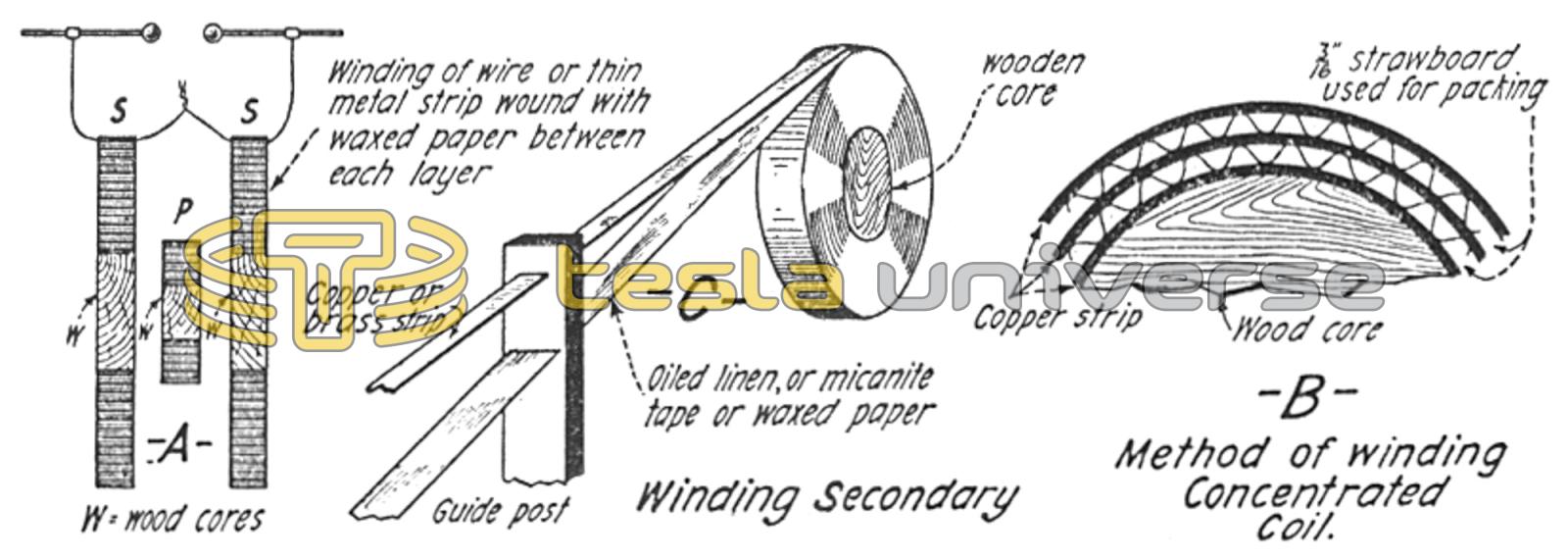
A very efficient type of Tesla coil is shown at “A”, where a single primary is placed between two secondary windings and in this way the magnetic flux from the single primary coil is effectively utilized. At “B” is shown a method of winding concentrated high frequency coils with copper or brass ribbon, using corrugated cardboard to separate the turns, while at “C” a special winding jig is illustrated for winding concentrated H. F. coils with copper ribbon and some good insulating tape.
The insulated stand, which the performer will need for many experiments, can easily be made of wood and the four wooden legs composed of the pins used for holding insulators on telegraph poles. The glass feet comprise four glass telegraph insulators or they may be porcelain, whichever is handiest to obtain. Four bottles can be used as legs, they can be attached with wooden pins in the necks.
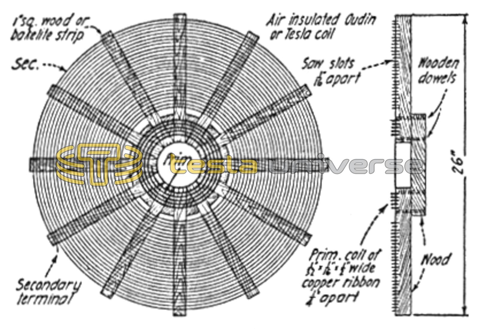
A front and side view of a spiral or pancake type high frequency coil which may be operated either with Tesla or Oudin connections. Wood strips will serve for ordinary uses, but hard rubber or bakelite strips are best.
Large vacuum tubes or a string of tubes can be lighted between two people, as shown at Fig. 3-C. Note that the lecturer stands on the insulated platform, while his assistant stands on the floor, or sheet metal, if found necessary, as mentioned above. At Fig. 3-D is shown how an electric duel is staged where a large Oudin coil is available, such as those used by public lecturers or theatrical performers. Here the insulated wire coming from the ball terminal atop the Oudin, is connected to a piece of metal, all of which is hidden by a rug. The lecturer picks up a fencing foil from a table and challenges anyone in the audience to fight him an “Electric Duel.” Due to the powerful charge available from the large Oudin, a spark several inches in length will jump between the foils when the would-be duelist causes his foil to approach that of the lecturer.
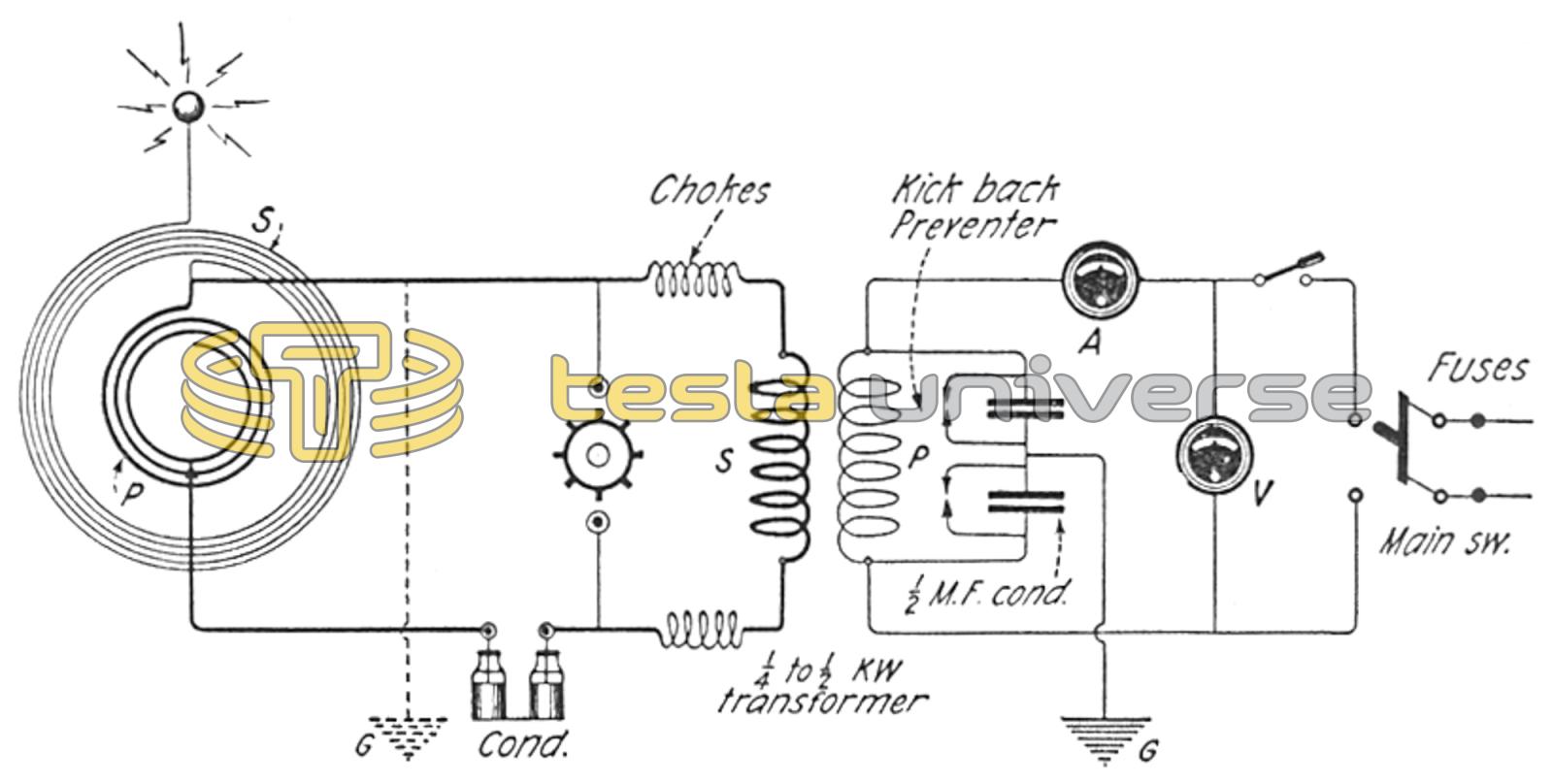
Complete hook-up of high frequency coil using Oudin connections, which gives a powerful unipolar discharge from the brass ball shown. A rotary or quenched spark gap is preferable for this apparatus, and in any case a kick-back preventer should be connected across the primary of the step-up transformer, to protect the electric service company's motor, as well as to prevent burning out lamps in your house, or in your neighbor's house.
Many other interesting experiments, some of them variations of those here described can easily be devised by the builder of the apparatus.
Large, High Frequency Apparatus
Something new in the style of presentation of the high frequency acts is shown at Fig. 4. The effect of this form of presentation is very mysterious to the uninitiated. All that the audience sees is a large spiral coil supported by strings and insulators from the ceiling, or else by means of glass rods on top of a table, the high frequency discharge taking place between the two brass balls shown. The secret of this apparently isolated coil, which the lecturer explains “gathers electrical energy from the atmosphere,” lies in the fact that the coil is placed but a few inches from the wall shown; and behind the wall in the next room or behind the canvas drop if this is used, is the primary winding of the Tesla coil. The thinner this wall is, the better, but, of course, the more powerful the apparatus, the greater this distance can be. A 1/4 to 1/2 K. W. step-up transformer giving 10,000 to 15,000 volts and preferably more, is suitable for presenting this act in a small way, but it is best to use at least a 1 K. W. transformer giving 15,000 to 20,000 volts. The high tension condenser may comprise several glass Leyden jars or else a number of glass plates, such as old photographic negatives, measuring about 8" x 10", from which the emulsion has been removed by soaking in hot water. If glass plates are used, about a dozen will be needed. Thin sheet metal or tinfoil leaves about 1 1/2" smaller in width and breadth than the glass plates, are placed between the latter and alternate lugs are connected together, as explained in detail below.
Figs. 5, 6 and 7, show details of a pancake Tesla coil which may be wound in two different ways. At Fig. 5 several suggestions are given which the experimenter will find of value in building a pancake style Tesla or Oudin coil. At Fig. 5-A is shown a very efficient arrangement for pancake type high frequency coils, where the primary, P, is placed between the two secondary windings S and S. To wind a concentrated or compact style of pancake coil, the windings may be made of thin copper or brass ribbon insulated or separated by some form of insulating material such as tape.