TCBA Volume 18 - Issue 1
Page 17 of 18
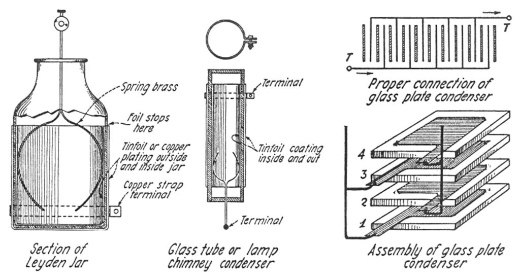
Several suggestions are here offered in the building of high voltage condensers. These condensers are usually made of glass but other materials, such as mica and sheets of bakelite, etc., have been used. The main thing to watch in building any high voltage condenser is the insulation, of course, and the metal plates charged with currents of opposite polarity should have a sufficient insulating space left all around their edges.
The primary winding, composed of the heavier metal ribbon, may be insulated by means of the paper strawboard used in packing glassware, etc., as seen in Fig. 5-B. To build a concentrated secondary coil after this fashion, a wooden core is used on which to wind the thin copper or brass strip, and at the same time a layer of oiled line, or micanite tape, is wound on and kept in alignment by means of the special guide posts having two slots as shown in Fig. 5-C. The ratio of the number of turns in the secondary and primary of the average Oudin coil is from 250 up to 300 to one. There are no figures available for designing these coils, owing to the great difference in the manner of insulation, and in the way the windings are spaced and arranged, so that the best rule will be found to build a coil of a certain size and try it out. If it does not give a sufficiently long spark or high enough voltage, more turns may be added. If there seems to be too much brush discharge or leakage between the turns, wind another coil with the turns separated a little farther.
Fig. 6 shows a type of air-insulated high-frequency coil which is best suited for Oudin style excitation and a number of which were built in an X-ray laboratory in New York City some years ago. To build this form of high frequency coil a number of wooden or better still bakelite, hard rubber or fiber strips are cut out and assembled on a wooden or other insulating disk, as shown. For use with a step-up transformer rated at 1/2 K. W. and giving 12,000 to 15,000 volts at the secondary, the air-insulated pancake transformer shown at Fig. 6, should have an outside diameter of about 26", and an inside diameter on the inner primary turn of 3" For the primary winding five turns of half inch copper or brass ribbon, 1/32" to 1/16" thick is placed in slots cut 1/4" apart, as the diagram indicates. Of course all the slots should be marked off carefully before the strips are assembled on the center disk, and then by placing them all together side by side, a slot can be cut simultaneously across all the strips.
The secondary or outer winding in this case may comprise about 150 to 180 turns of No. 28 and No. 30 bare or insulated copper magnet wire, each turn spaced about 1/16" from the next. With this style of winding the coil is practically only suited for Oudin connection, and the primary and secondary are joined together as shown in the diagram at Fig. 7, taking care that the current passes around the primary and secondary in a continuous or in the same direction as explained for the bottle Oudin.
We Pay a Cent a Word
WE want good electrical articles on various subjects, ancl here is your chance to make some easy money. We will pay one cent a word upon publication for all accepted articles. If you have performed any novel experiments, if you see anything new electrical, if you know of some new electrical stunt, be sure to let us hear from, you. Articles with good photographs are particularly desirable.
EDITOR.
Fig. 8 gives details of H. T. condensers both of the Leyden jar and glass plate types. With all larger sizes high frequency transformers it is the usual practice to provide clips on the end of flexible heavy insulated cables or leads from the spark gap and condenser circuit, so that various numbers of turns or even a fraction of a turn may be included in the primary circuit. The adjusting of the number of plates or jars in the condenser, as well as the number of primary turns of the Oudin connected in the circuit, is known as “tuning the set.” On all high frequency sets it is best to place choke coils on the terminals of the step-up transformer, as shown at Fig. 7. Each choke coil may comprise about two dozen turns of No. 24 bare or insulated magnet wire, wound on a porcelain tube with the turns placed a small distance apart. It is the object of these choke coils to prevent high frequency surges from passing back into the transformer and possibly burning it out.
A quenched or rotary spark gap will be found very efficacious in all high frequency sets, except in the smaller ones, where they are not necessary, as the tendency with large H. F. sets is to cause arcing at the spark gap after it has become heated; this tends to destroy the oscillatory discharge effect and lower the frequency, besides reducing the length of Tesla or Oudin discharge in any case.
Conical Oudin Coil for use with 1 K. W. Transformer
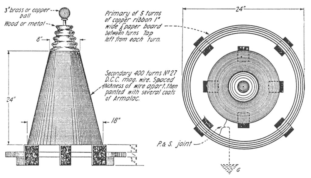
For those experimenters who have available a step-up transformer rated at 3/4 ths to 1 K. W. or more, the conical type, large size, Oudin coil shown at Figs. 9 and 10 will be found very efficient and capable of giving a spark 3 to 4 feet in length. This coil as built was described in detail in the May, 1917, issue of “Electrical Experimenter.” All of the working data for building this coil is given herewith, however, and with a little care in the workmanship and the adjustment of the apparatus, all of the results obtained by Dr. Strong should be readily obtained with it.
The Oudin coil itself is composed of a primary and secondary as usual. The primary comprises five turns of 1" copper ribbon, 1/16" thick, wound in a radial or spiral manner. The secondary form may be built in several ways and resembles a peach basket. In building wooden forms for high frequency coils no matter of what size, no nails or other metal parts should be tolerated. Wooden pegs and glue should be used throughout. The conical secondary form here required for building the 1 K. W. Oudin may be built up with about 8 to 10 strips of wood evenly spaced around several wooden disks of the proper diameter, so as to form a tapering core. Around this wooden form several thicknesses of ordinary wrapping paper are wound, each layer is shellacked thoroughly, and in this manner a reasonably smooth contour will be had.
This large demonstration type high frequency coil, to be operated on the Oudin principle, will yield a veritable tree of sparks at the brass ball terminal when excited by a one kilowatt 20,000 volt step-up transformer. The primary of this coil is wound with heavy copper strip.


