
TCBA Volume 6 - Issue 1
Page 12 of 18
Membership Activity
George Westwater
President, Multiple Analog Device Scientific Co.
Brookhaven National Laboratory
Building 901A
Upton, NY 11973
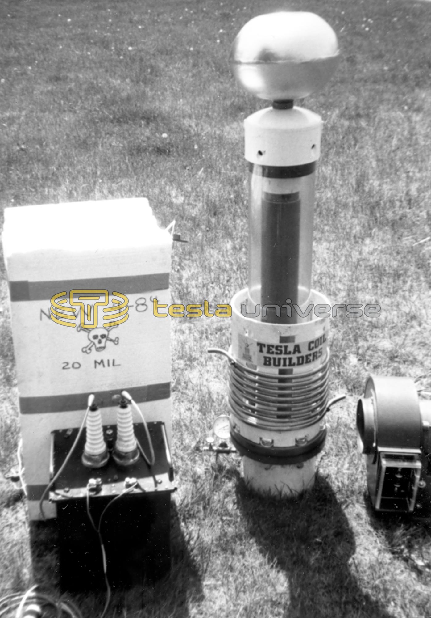
This Tesla coil project is unlike any other that has appeared in TCBA NEWS in that it is sealed in a container and pressurized with Sulphurhexafluoride(SF6). This procedure eliminates any corona loss or breakdown between the primary and secondary. Consequently, it can withstand a very high input voltage.
The secondary coil is wound on a 3" (ID) PVC pipe and is 24" in length. The #28 gauge enameled wire is wound into a threaded form giving 30 turns to the inch. The secondary coil is given a spray of krylon immediately after winding in order to prevent the wire from stretching and sagging.
After winding the secondary, it is placed inside a 6" diameter clear lucite tube and is sealed at both the top and bottom with caps. The primary is wound on an 8" diameter PVC form.
Mr. Westwater uses his own home made capacitor. It consists of foil between polyethylene layers (see the large white box). The total capacitance is .0126 mfd.
The project is powered by a neon sign transformer that has been redesigned to give 15KV at 200 ma. A plain spark gap is used but it is aided by a blower system. This helps to keep the gap cool and prevent arcing.
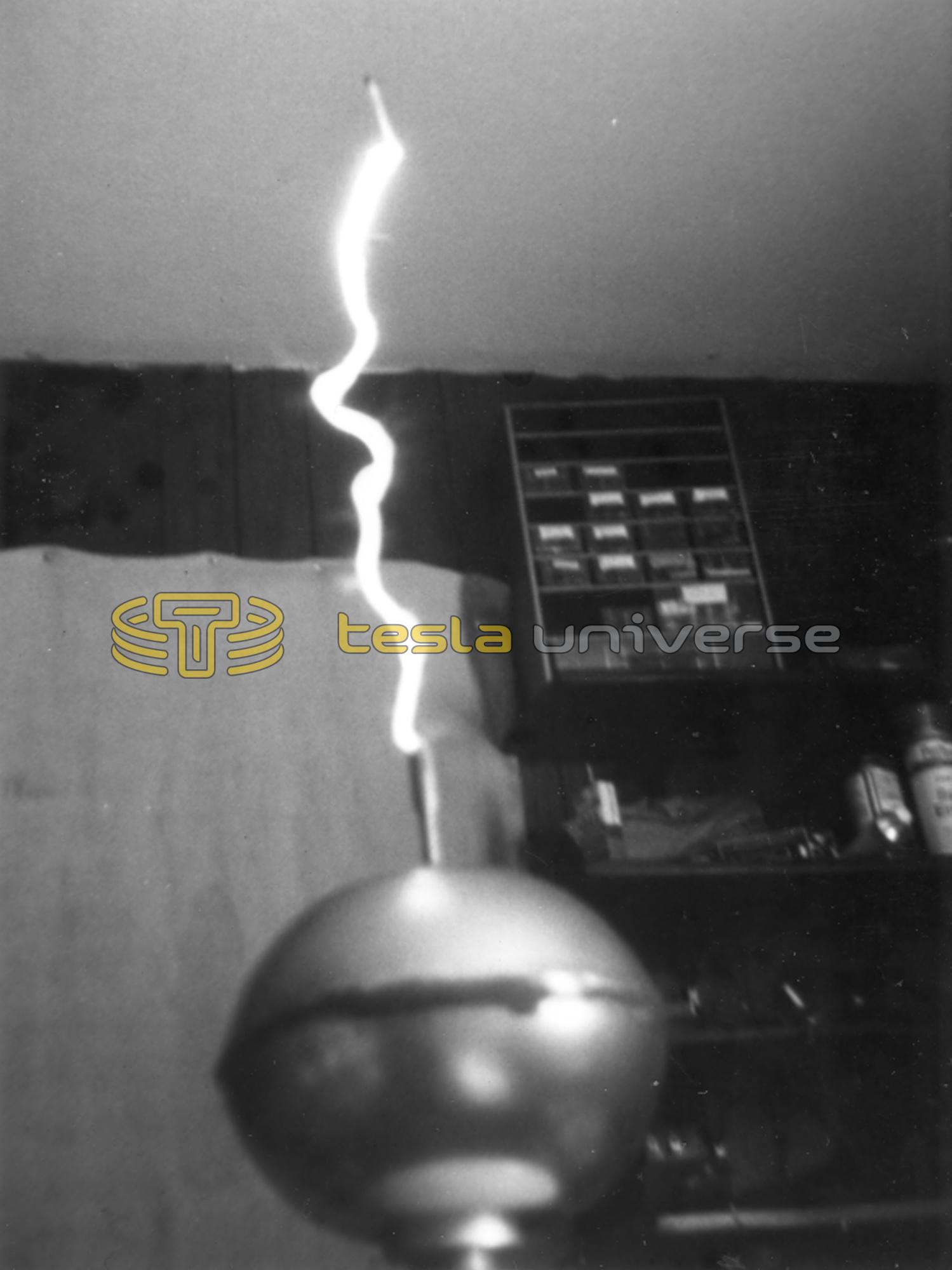
George emphasizes the 1/4-wave principle and try's to bring both the primary and secondary into tune as closely to this as possible. He finds the 1/4-wavelength by both calculation and measurement. Tuning is done by slight alteration of the primary inductance. This attention to details is evident in the photo showing a healthy spark. As you can see, it is limited only by the distance to ceiling.
George Westwater also works on other high voltage devices including Van de Graaff accelerators, transformer design, and capacitor construction and design.
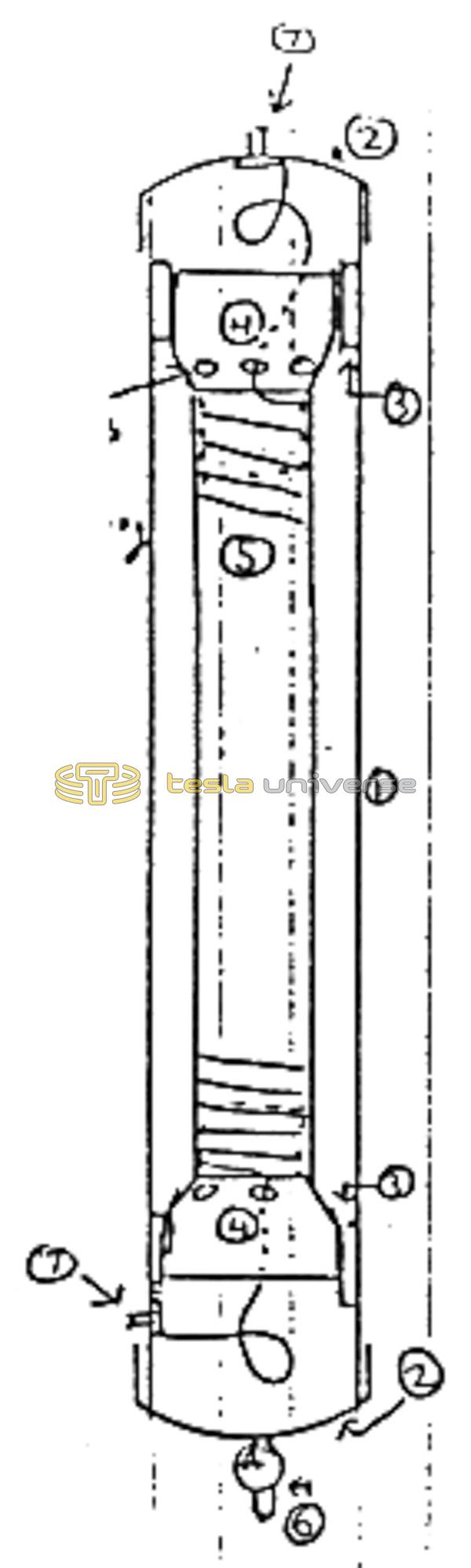
- 40" X 6" diameter tube
- Two 6" domed caps
- Two 6" to 4" reducing donuts
- Two 4" to 3" reducing bushings
- Secondary coil assembly
- Fill valve
- Two 1/2" X 20 terminating connections