TCBA Volume 6 - Issue 1
Page 9 of 18
Tesla Coils Resurrected
Laboratory Tesla Coil
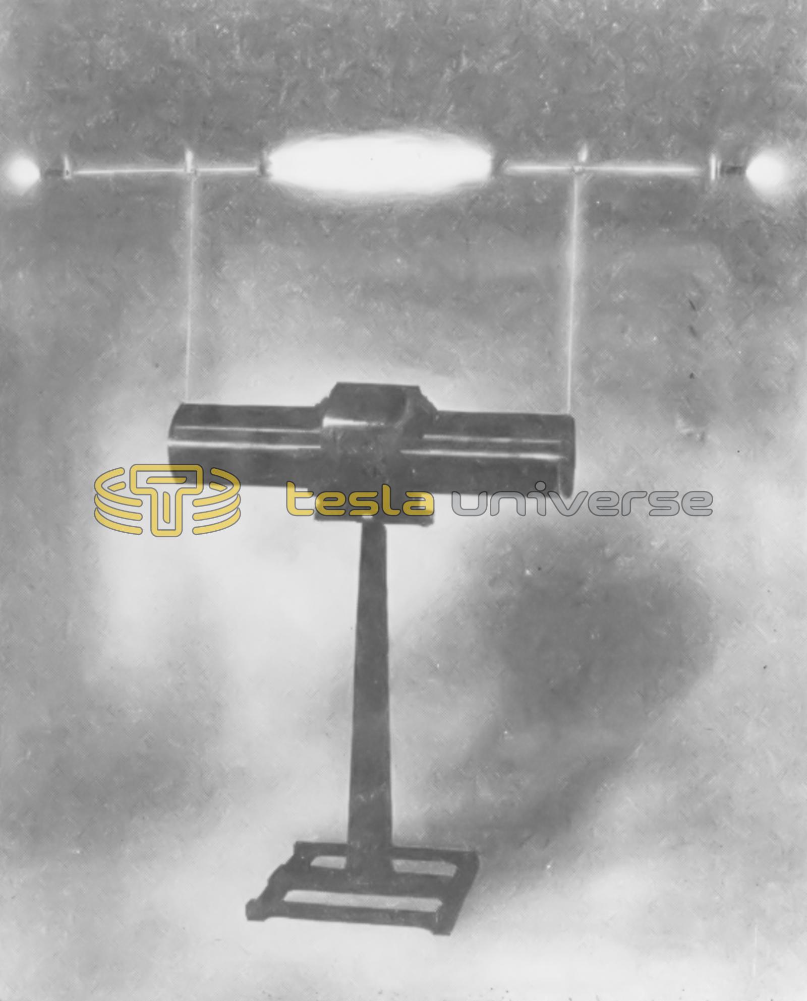
The present article will deal with the construction and operation of the Tesla coil shown in the illustrations. This coil is capable of delivering a heavy 32-inch spark - a spark almost as long as the coil itself. So many spectacular experiments and practical applications of the Tesla coil have been described in back numbers of PRACTICAL ELECTRICS that it will be unnecessary to mention them here. The experimenter who is fortunate enough to own a 1-kilowatt Tesla coil outfit may find many new and interesting applications of high frequency currents not mentioned in books or magazines.
The design of a Tesla coil would entail so many mathematical calculations that it is better practice to determine the size and number of turns on the coil by trial or from previous experience. However, the open circuit or secondary winding may be calculated from formulas given in handbooks, so that this circuit will have a natural period of oscillation or wave-length equal to that of the primary circuit; the primary circuit is then made variable and is accurately tuned to the secondary circuit. The spark gap and its connections greatly affect the wave-length of the secondary circuit and must be taken into consideration when designing the coil.
The secondary circuit of this coil has a natural wave-length of about 600 meters, and the frequency of oscillations is therefore around 500,000 cycles per second. At this frequency the discharge may be taken through the body without harm, but a sensational shock will be experienced.
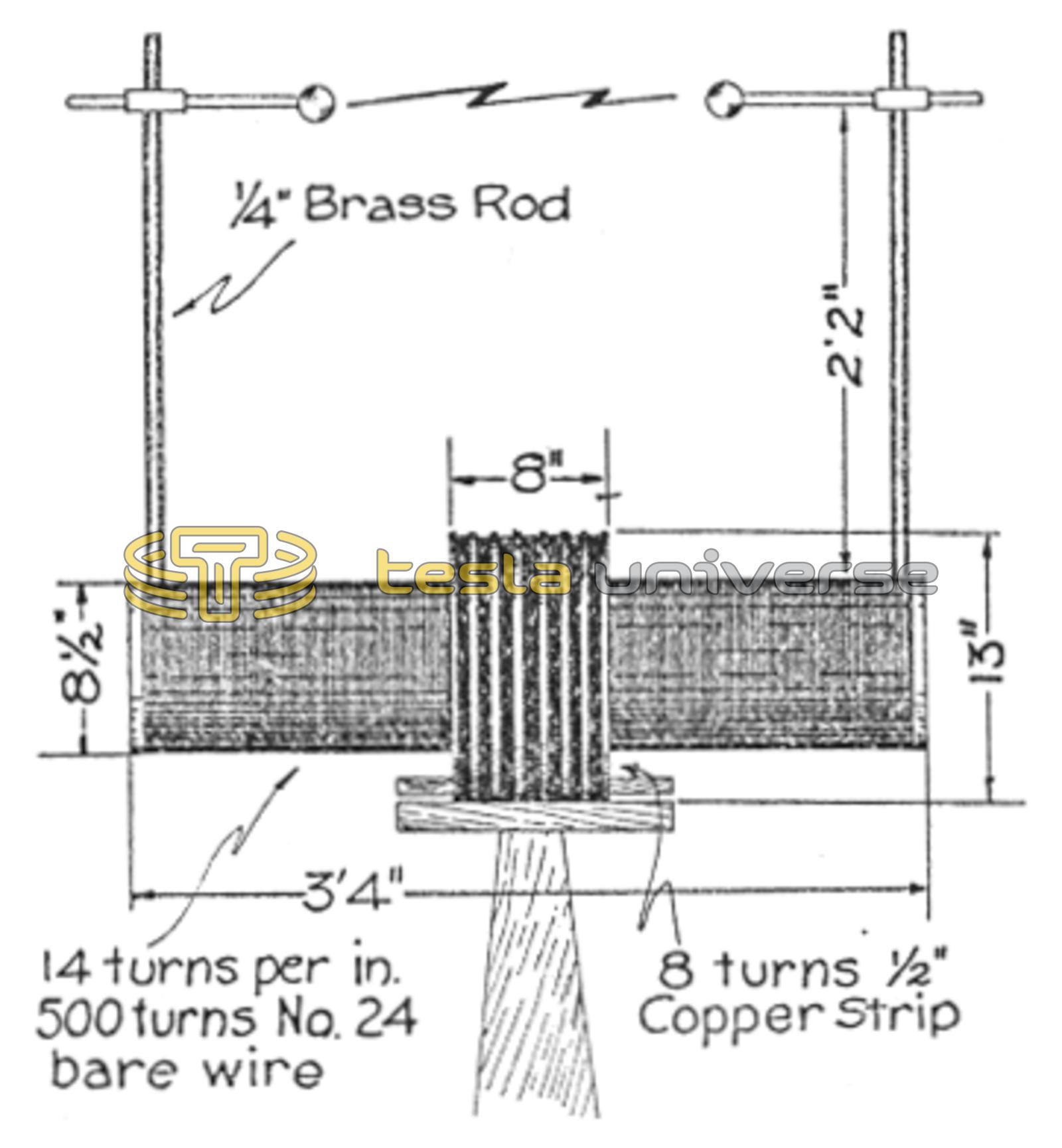
The drawing shows the dimensions and windings of the coil. The secondary coil consists of 500 turns of No. 24 B. & S. bare copper wire bound on a bakelite tube 8 1/2 inches in diameter by 3 feet 4 inches long. The turns are spaced so as to give 14 turns per inch by winding a string on the tube with the wire, after which the string is removed and the winding given a coat of shellac. The primary winding consists of eight turns of bare copper strip one-half inch wide. It is also spaced, as shown, on an 8-inch tube 13 inches in diameter, and coated with shellac. A copper lug is soldered to each turn so that connections can be made for tuning purposes.
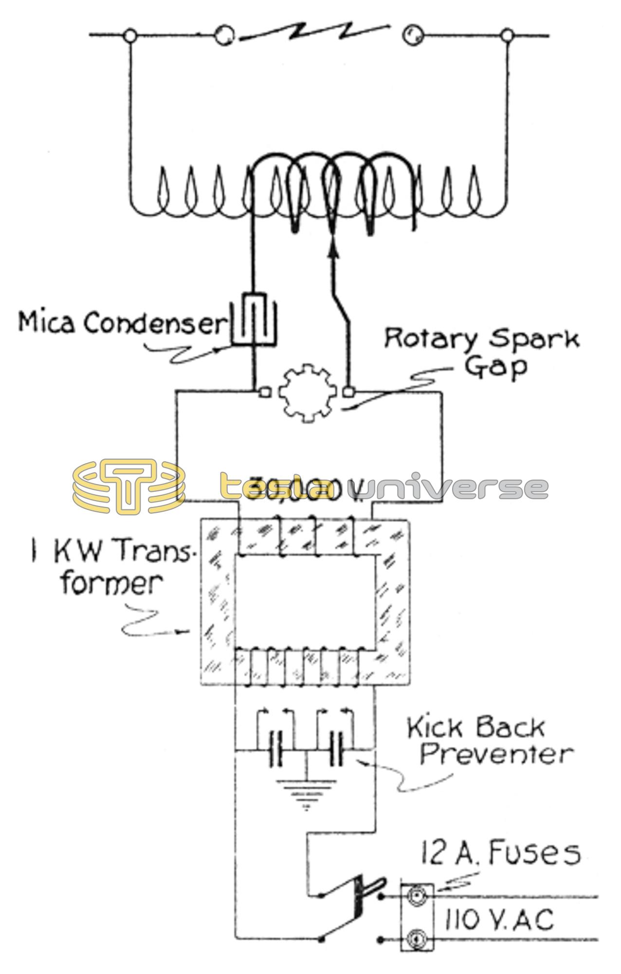
The diagram shows the connections of the Tesla coil. The 110-volt alternating current line is connected through a set of fuses to a double-pole, single-throw switch. This switch connects the line to the primary of the 110 30,000-volt transformer. A kick-back preventer is connected across the primary of the transformer. This allows a free path to ground for high frequency surges which would otherwise blow the fuses or destroy the insulation on the 110-volt line. This kick-back preventer consists of two one-half mfd. paper condensers connected in series and grounded at the middle point. A needle gap is placed across each condenser to protect it from being punctured by extremely high voltage surges. The secondary of the transformer connects to the rotary spark gap, mica condenser and primary of the Tesla coil.
There are two sources of trouble in operating a Tesla coil on a 1-kilowatt 30,000-volt transformer. One source of trouble is in the rotary spark gap. Unless the gap electrodes are spaced far apart and the disc run at high speed, the spark has a tendency to draw out and jump from one electrode to the other without being interrupted. The other source of trouble is in the high voltage condenser. If glass is used for the dielectric it will be necessary to use very thick plates, which make a bulky condenser, or to use two condensers in series. This will require four times as many plates for the same capacity as a single condenser.
The dielectric used in this condenser was of a mica compound, made up of layers of thin mica sheets shellaced and pressed together to a thickness of three-thirty-seconds inch. A piece of this stock, 12 inches by 12 inches, was tested by subjecting it to a high voltage. Two electrodes, one inch in diameter, were placed on each side of the sheet at the center and leads run from these electrodes to the terminals of a high potential testing transformer. The voltage was applied and gradually increased to determine the break-down voltage of the mica sheet, but the sheet would not puncture; and the current arced around the edge of the sheet.
The condenser was made up of 20 of these sheets coated on each side with tinfoil sheets, 8 inches by 8 inches, and immersed in a tank of transil oil. This condenser worked perfectly; there was no more trouble from punctured plates and corona losses were reduced to a minimum. However, as the condenser was used, the efficiency dropped and losses in the condenser increased. In about half an hour of constant use the condenser was too hot to touch and the oil was nearly boiling. When cool the condenser was as good as ever. This condenser gives excellent results for intermittent use, but is not very efficient for continuous service.
For other articles on Tesla apparatus we wish to refer our readers to the November, 1921, and the September, 1922, issues of PRACTICAL ELECTRICS, in which some very interesting experiments are to be found.