
TCBA Volume 6 - Issue 1
Page 17 of 18
Tuning your Tesla Coil with Variable Capacitors
by
Tom Lee
8219 East Meadowbrook Ave.
Scottsdale, Arizona 85251
When you buy your main primary energy-storage capacitor (or resonating capacitor), it is likely that you will purchase a used unit to keep costs sensible. Used components, however, are seldom exactly what you need. Even when placing them in parallel, series, or parallel-series connection, you may only come close to the exact value. What is needed is a way to fine tune the coil. A variable capacitor may be inserted to provide the optimum capacitance.
Although a well constructed Tesla coil may be sensitive to capacitance changes as little as 500 pF or 0.0005 uF, a large transmitting air variable with a plate spacing sufficient to give it a rating of a typical primary voltage will reduce the capacitance to perhaps 50 to 200 pF or 0.0002 uF. Since the primary capacitor in most coils is in the range of from 0.005 to 0.05 uF, the 50 to 200 pF is going to have little effect. If plates were added to the transmitting variable capacitor to provide an effective capacitance, it would be many feet long.
There are air variables around with values as high as 2,000 pF or 0.002 uF. The plate spacings are small, however, and the breakdown voltage is a few hundred volts. These would have enough capacitance but they would arc over. The following information, taken from my book,1 presents a solution to this difficult engineering problem.
The circuit schematic of a simple coil shown at the right indicates the 4 capacitances associated with a Tesla coil. The primary energy-storage capacitor is C1. The trimmer capacitor is shown as C2. The distributed capacitance of the secondary becomes C3 and the secondary terminal capacitance is C4. Only C2 is easily changed.
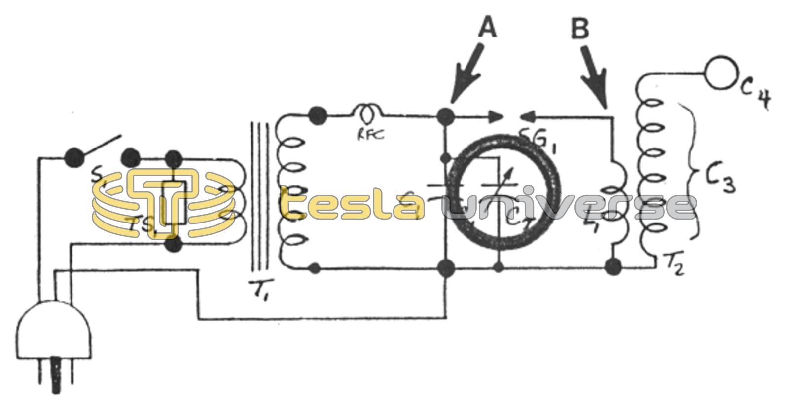
Consider what happens during coil operation. The primary capacitor C1 is charged to a high voltage 120 times a second by the transformer T1. It is when the spark gap breaks down that energy is dumped into the primary, a relatively low impedance and low resistance circuit. This results in a high peak current in the primary that may be several hundred to several thousand amperes (depending upon a variety of parameters). The voltage across the primary, however, is low. This is the condition that makes it possible to tune a coil with a variable capacitor (when inserted at the right location of the circuit).
The most practical type to use is the old 365 pF per-section tuning capacitor used in old tube type radios. They commonly had three sections for a maximum parallel value of 1095 pF or 0.0011 uF. Occasionally, they had four sections yielding a maximum parallel capacitance of 1460 pF or 0.00146 uF - still not impressive.
However, if you oil-immerse these capacitors the capacitance values become multiplied by the value of the dielectric constant of the liquid. In the case of mineral oil, with a constant of about 2.2, the maximum value for a four-section unit now becomes 3212 pF or 0.0032 uF - a significant value. The breakdown voltage of the capacitor will rise by as much as a factor of ten.
Remember to disconnect the little compression mica trimmers by cutting the straps. Next, examine the circuit schematic above. If the oil-immersed variable cap is inserted into the circuit across the primary at B, instead of at point A, it does not have to withstand the full transformer peak voltage (RMS nameplate voltage multiplied by 1.41). You can use a sensibly-sized capacitor to tune a very large coil with this method. This is essentially Nikola Tesla's idea which he patented December 8, 1891.
- HIGH VOLTAGE GENERATION USING AIR-CORE SOLENOIDS, $25 postage paid (allow 30 days for delivery).