Nikola Tesla Books
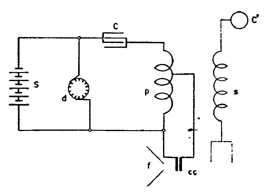
A solution which I have before described is offered in the following scheme, illustrated diagramatically below.
S is a source of preferably direct current as a powerful battery or dynamo, C a condenser which is connected with a primary p and break d as usual in an oscillator. The break d is such that at the number of breaks resonance is obtained.
A secondary s is provided which is connected to the ground and an insulated body of capacity and elevated as shown, and normally the adjustment is such that the secondary with its capacity and self-induction is in resonance with the primary p. From the latter a shunt is made by two contacts c c preferably of carbon. Normally these carbons touch loosely but by speaking upon funnel f they are harmonically pressed together and the primary current is diverted thus destroying the resonance and greatly diminishing effect in the secondary rhythmically with the undulations of the voice. In this manner very minute variations in the contact resistance are made to produce great variations in the intensity of the waves sent out. The breaks at d must be much above undulations of the voice.
Colorado Springs
June 14, 1899
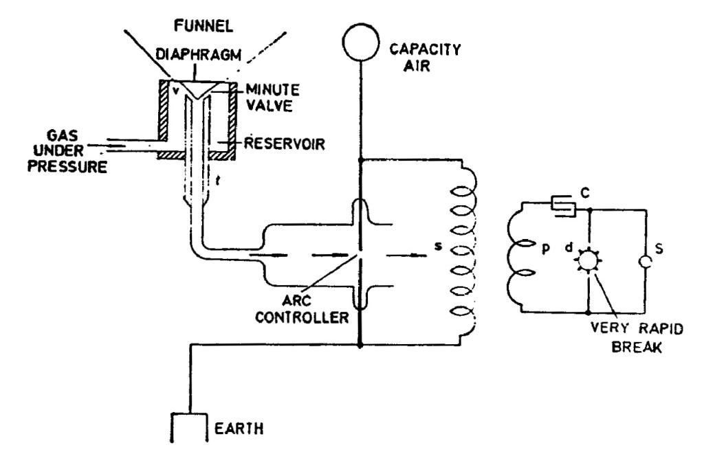
The following arrangement, considered before in a general way, seems to be particularly suitable for telephony at a distance without wires and for such purposes where it is necessary to effect control of a powerful apparatus by feeble impulses such as those produced by a human voice.
The idea is to use an ordinary oscillator, preferably one operated from a source of direct currents with a break (mercury or simply an air gap) which is much higher in
3*
35
Tesla: "Phenomena of alternating currents of very high frequency", The El. World, Febr. 21, 1891, A-3.
"Electric discharge in vacuum tubes", The El. Engineer, July 1, 1891, A-16.
June 13-14
From the very start of his work on wireless transmission of signals in 1892 - 1893 Tesla advocated the use of continuous HF current, while other experimenters were working with damped impulses. The advantage of continuous currents is particularly great in the transmission of continuous signals, such as speech. The entries for the 13th and 14th of June describe two modifications of the HF oscillator which could be used for amplitude modulation. These two circuits were probably in fact the first modulators in the history of radio. It is not known whether Tesla carried out any experiments with this apparatus, but similar ideas were implemented later(19).
Tesla's notes illustrate how carefully he studied the design, from the power supply to theoretical aspects such as the ratio of the maximum modulation frequency to the carrier frequency.
The transmitter using "controlled arc" modulation of the oscillator power described in the entry of June 14th produces amplitude modulated wave by varying the carrier power about a mean value. The modulating signal can be of low power, so that the device as a whole can also be considered a frequency-shifting amplifier.
June 14
The transmitter with the output power modulation by means of "regulating arc" represents the variation with "air" microphone. The oscillator scheme remained the same as the one of June 13. The remark on the advantage of supply from a direct current source is repeated (probably due to parasitic modulation which would be caused by an excitation generator of alternating low frequency current). Transmitter output power modulation is now performed in a secondary-antenna circuit, by means of an electric arc of which the intensity is varied with sound pressure variation rhythm. The sound is regulated by gas flow under the pressure of special valve v which is regulated by moving pipe t.
The amplitude modulation is achieved by carrier power variation around the average value at the rhythm of the modulated signal. Modulated signal is of small power and therefore this device as a whole could be made as an amplifier with frequency conversion.


