Nikola Tesla Books
Compared with the first winding (14 turns far apart) the second winding was better because of both higher self-induction and greater mutual induction coefficient.
Measurement of capacity of condenser in sections:
The condenser was compared today with 1/2 mfd. standard by wirebridge and telephone receiver, according to the Maxwell method. There are 80 sections in the condenser, 40 on each side, which can be connected by plugs as desired.
They are: 1 + 21 + 22 + 5 + 10 + 10 + 20 + 30 = 80
The measurements made by Mr. L. today gave 0.153 mfd per unit.
This to be verified.
Colorado Springs
June 19, 1899
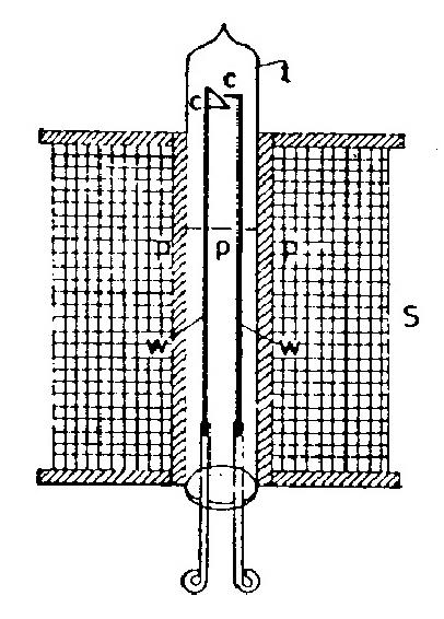
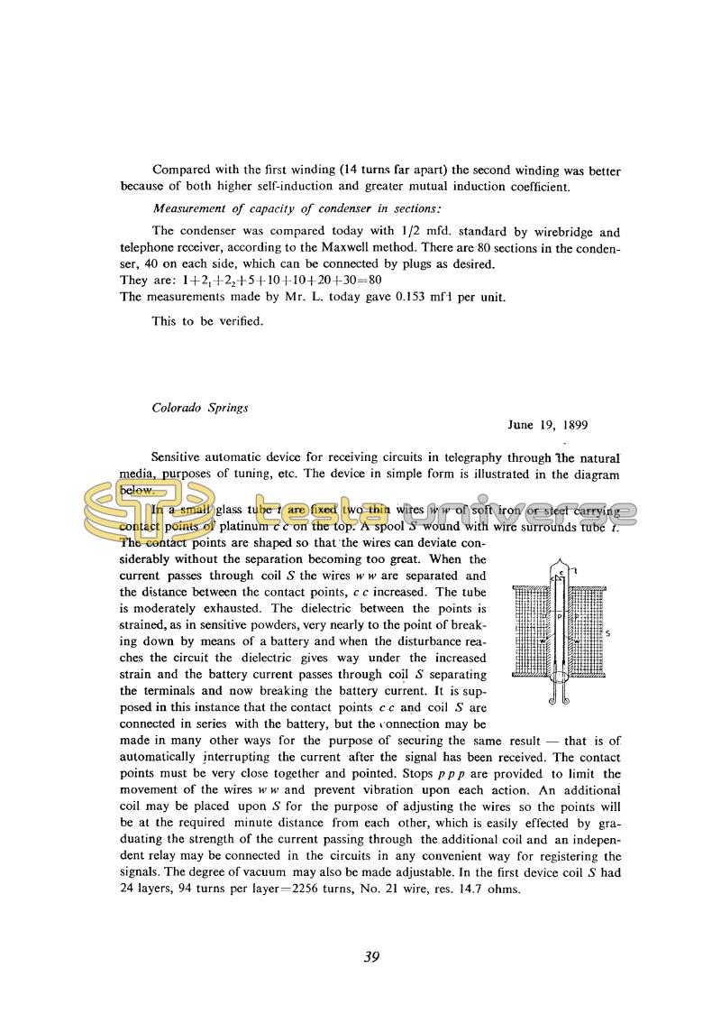
Sensitive automatic device for receiving circuits in telegraphy through the natural media, purposes of tuning, etc. The device in simple form is illustrated in the diagram below.
In a small glass tube t are fixed two thin wires w w of soft iron or steel carrying contact points of platinum c c on the top. A spool S wound with wire surrounds tube t. The contact points are shaped so that the wires can deviate considerably without the separation becoming too great. When the current passes through coil S the wires w w are separated and the distance between the contact points, c c increased. The tube is moderately exhausted. The dielectric between the points is strained, as in sensitive powders, very nearly to the point of breaking down by means of a battery and when the disturbance reaches the circuit the dielectric gives way under the increased strain and the battery current passes through coil S separating the terminals and now breaking the battery current. It is supposed in this instance that the contact points c c and coil S are connected in series with the battery, but the connection may be made in many other ways for the purpose of securing the same result ñ that is of automatically interrupting the current after the signal has been received. The contact points must be very close together and pointed. Stops p p p are provided to limit the movement of the wires w w and prevent vibration upon each action. An additional coil may be placed upon S for the purpose of adjusting the wires so the points will be at the required minute distance from each other, which is easily effected by graduating the strength of the current passing through the additional coil and an independent relay may be connected in the circuits in any convenient way for registering the signals. The degree of vacuum may also be made adjustable. In the first device coil S had 24 layers, 94 turns per layer=2256 turns, No. 21 wire, res. 14.7 ohms.
39
June 18
The secondary circuit was modified by the addition of another coil, altering its response to the primary and the spectrum of the oscillations. Tesla had already found in experiments in New York that this "extra coil" had a good effect. This coil was not inductively coupled to the transformer (some coupling probably existed, though weak).
June 18
So far Tesla didn't show the method by which to determine the oscillation frequency, but it is clear that he already had some results. When looking for the mismatch reason of measured and calculated value he tries one new modification of the high frequency transformer. He makes a new coil, which is connected by its one terminal to the open secondary terminal, and then a considerable voltage increase at the other terminal of the new coil is achieved.
By adding the coil in series with the secondary, Tesla changes the oscillator secondary circuit.- So the secondary reaction to the primary becomes different and changes the oscillations' spectrum. The effect of the "additional" is known to Tesla from his experiments in the New York laboratory. This coil is not in inductive link with the high frequency transformer (link probably exists, but poor).
The analysis of Tesla's oscillator with "additional coil" could not be performed according to Oberbeck Theory because the secondary circuit is changed. Instead of capacitance C2 (please see Appendix: Tesla's Oscillator) now the parasitic secondary coil capacitance exists with which in parallel is connected the series combination of "additional coil" with quite indefinite parasitic capacitances. For the purpose of orientation when determining the secondary circuit Tesla mentions that the secondary wire length has to amount to one quarter of a wavelength. This requirement appears in patents from 1897(13,14,15). Actually the wire will be shorter, because the speed of current propagation along the coil is lower than along the real conductor.
The measurement of oscillator circuit parameters he performs on a rewound secondary. He gives first capacitance measurements in primary oscillator circuit.
June 19
Continuing his study of the receiver components referred to between 9th and 11th June, Tesla describes a sensitive detector using the attractive force between the plates of a charged condenser. Descriptions of allied devices are to be found in several of Tesla's patents. In patents(8) and (9) this effect is used to periodically make the receiver circuit when main condenser charges up sufficiently (there is no preexcitation nor quenching, since the circuit quenches itself when all the stored energy gets discharged). A fuller description, where it is noted that the performance of the device is improved under reduced air pressure, may be found in patents(70).
June 19
Continuing the studies on receiver elements between June 9 and 12, Tesla describes one "sensitive device" for detection of small voltages. Device in question used the attraction force between layers of capacitors. Capacitor layers are two wires made of soft iron. Dielectric between these wires is under influence of a field from auxiliary source - battery, and that field is such that additional low voltage causes the wires' attraction. It is particularly interesting that wires are in the coil field (that's why they are made of soft iron) so the device could be de-activated by current action through the coil. De-activating current is obtained when contacts on wires touch one another. The magnetic field in the coil magnetizes the iron wires and they repel each other.
The sensitive device which operates on the capacitor layers attraction principle is described in several of Tesla's patents. In patents(8,9) mentioned device is used for periodical receiver turn-on when sufficient energy is accumulated in main capacitor of the receiver (the pre-excitation is not planned and therefore there is no deactivation, because the device switches itself off when all energy in the circuit is used up). A more complete description, along with note that operation of this device could be improved by placing it in a space with rare air is given in patents(35,36).


