August 3-14
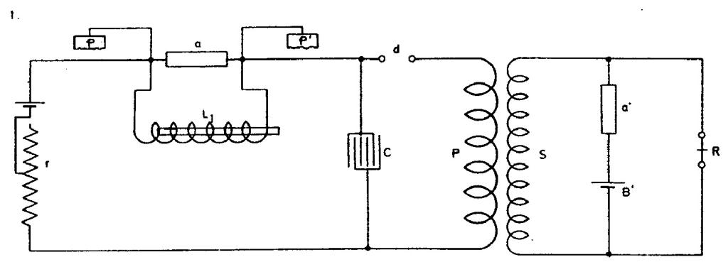
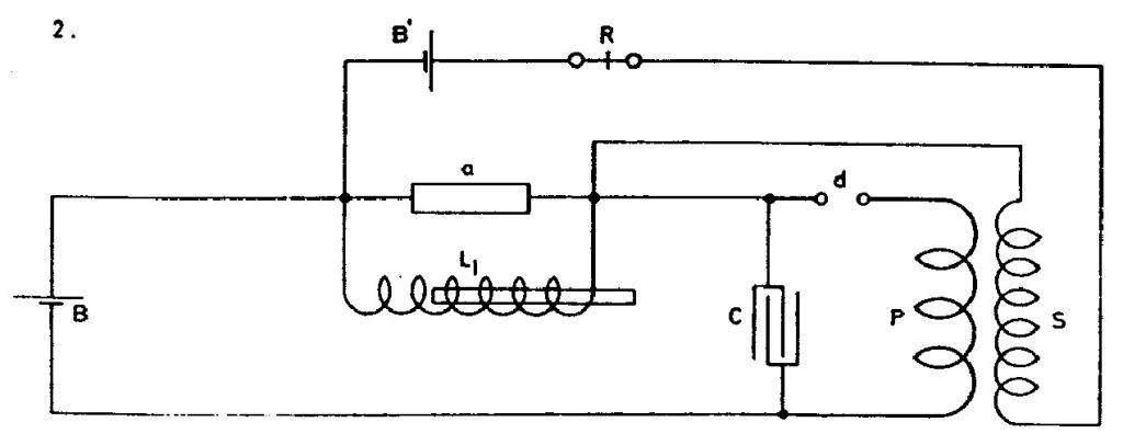
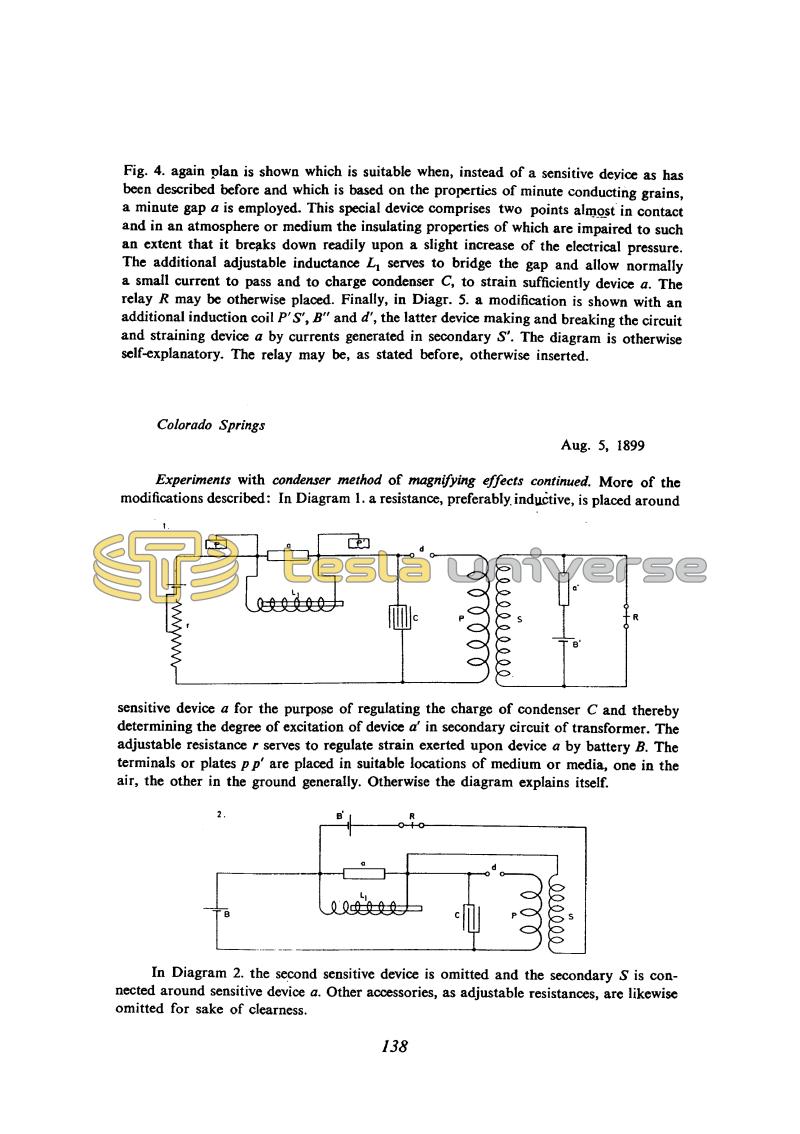
These experiments are a continuation of some earlier research. Here Tesla investigates various modifications of his "condenser method of magnifying effects". All the circuit diagrams of receivers, over 50, include at least one battery, sensitive device, condenser, rotary interrupter and HF transformer. Some of them show a relay for registering the signal received, while in others its presence is understood. Likewise, in all except one case (5 August, Fig. 1) the plates which brings the excitation to the sensitive device are not shown. Tesla says that these plates can be in one or two media, meaning that both can be in the air, both in the ground, or one in the air and the other in the ground, preferably elevated. In the patent(8), referring to these plates, he also says: "... they may be connected to conductors extending to some distance or to the terminals of any kind of apparatus supplying electrical energy which is obtained from the energy of impulses or disturbance through the natural media."*
As regards mode of operation, the various receivers have in common that the sensitive device is biased by a battery. They also include a Tesla oscillator (clockwork rotary interrupter) which creates an added bias on the sensitive device (or devices). This AC pulse bias acts as positive feedback, avalanching the sensitive device into conduction as soon as an arriving signal starts to cause some change. In the receivers with two sensitive devices the one which receives the external signal is usually in the primary side and the other, which activates the relay, on the secondary side. When there is only sensitive device it usually shunts the transformer secondary (which has a high impedance so as not to reduce the performance of the device), thus creating an efficient feedback loop.
A general feature of all Tesla's receivers is their delicacy. Very careful adjustment was necessary to get the sensitive device at the threshold of avalanching. Most of the sensitive devices were rotated (see June 23rd) so that they were only good conductors during the action of a signal. In some cases, however, this did not achieve satisfactory deactivation of the coherer. Then he used an electromagnetic buzzer to periodically interrupt the excitation of the sensitive device (see Fig. 2 of August 8th). Probably the circuit in Fig. 2 gave him the idea for that in Fig. 3, where the rotary interrupter is replaced by a buzzer as an electromagnetic interrupter. He then used a buzzer in various other configurations (Figs. 5 and 6 of August 8th), with the aim of reliably biasing the condenser, and hence also the sensitive device, to threshold.
Tesla did not measure the sensitivity of his receivers by any definite method, but there is no doubt that he did compare them in some way. From his notes very little can be deduced about their sensitivity, i.e. the power required to activate them. A rough idea is given by data from July 4th, when he used similar receivers to register electrical discharges. He estimated that he registered waves produced by lightning at least 200 miles away, and continued to receive signals (at periodic intervals) later when the weather had already cleared. He records that with the receiver shown in the figure of July 28th he was in one instance able to register lightning discharges at a distance of 500 miles. He estimated the distance from the periodicity of the signals as the storm moved away.
* It is interesting to note a similarity of such receiving system and the contemporary ELF grounded wire radiator. In the Nikola Tesla Museum in Belgrade few drawings, showing something that resembles a single grounded wire radiator and a parallel array ELF antenna(72), are found.


