TCBA Volume 10 - Issue 1
Page 9 of 18
Tesla Coils Resurrected
A Small High Frequency “Oudin” Coil
The high frequency transformer here described is of the Oudin type. All that is necessary to use in conjunction with it are a small wireless transformer or spark coil, a high potential condenser, and spark gap. The discharge obtained when the coil is excited by a 1/4 K.W. transformer will be from nine to twelve inches in length, while the spray discharges will reach out to still greater lengths. The results obtained with this small coil will thoroly repay the builder for the few hours spent in the construction of this simple, yet intensely interesting piece of apparatus.
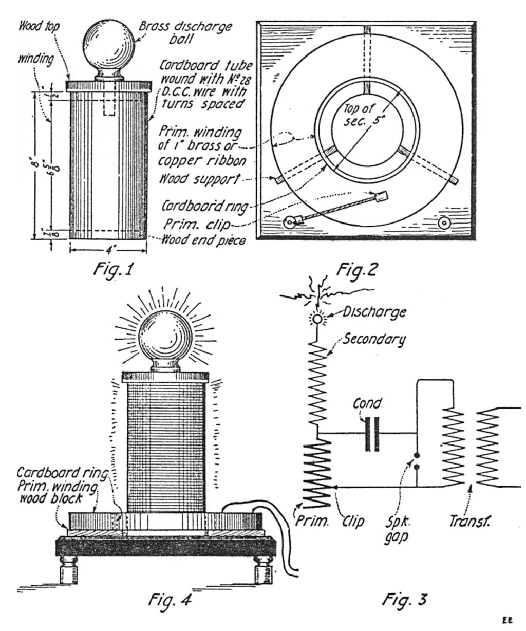
The secondary of the transformer is shown in Fig. 1. The cardboard tube, upon which the wire is wound, might well be a round “Quaker Oats” box cut to length. It should be well shellacked inside and out, so as to keep out the moisture. Two wooden ends should be turned or sawed out, and for the sake of appearance should be nicely stained and varnished. A discarded ball from a brass bed will be found to suit very well for a discharger. The wire for the secondary should be numbers 28 to 30 B. & S. D.C.C. or S.S.C. wire. The winding must be done on a lathe or else on a simple winding rig, as it cannot be evenly wound by hand. The turns are separated with a thread wound on with the wire. After the wire and thread are wound, the whole should be given two or three liberal coats of shellac (or better, “armalac”). The upper end of the winding should be fastened to the brass discharge ball. This finishes the secondary coil.
The primary is very easily constructed. It is made of one-inch copper or brass ribbon. The inside turn is taped to a cardboard ring, about 5 in. in diameter, and one inch high. This is shown in Fig. 2. The ribbon should be wound tightly, the turns separated by thin corrugated paper, such as used in packing boxes. The strip of paper should be about 5/8 inch wide, so as to allow sufficient surface of the ribbon exposed to make a variable contact with the helix clip. After nine or ten turns have been wound, the spiral should be tightened and taped on the outside. This makes a quite firm winding. The inside turn is connected to the lowest turn of the secondary, see diagram Fig. 3. Also a wire is led from this connection to one binding post. The clip is connected to the other post by a piece of high tension cable. The primary rests on wood supports, which may be of any convenient size. The base should be of 3/4 in. wood, and 11 inches square. The edges should be beveled. Porcelain knobs are glued under the corners by means of wooden dowels inserted into the base, as shown at Fig. 4. The complete hoop-up is shown at Fig. 3. Fig. 4 shows the transformer assembled. In operation, the clip should be moved from turn to turn, until the best discharge is obtained. It might be well to say that the current from the secondary is of such high frequency that it is entirely harmless when taken thru the body, providing the spark is allowed to jump to a piece of metal held in the hand, and not to the skin direct.
Contributed by G. W. COOKE.
(Editor's note: This is another example of the confusion that existed between Oudin and Tesla coils. The circuit diagram correctly shows the Oudin coil circuit. We see here a primary in the form of a helix with its upper turn connected to the lower turn of the secondary. In the actual construction, the primary takes the form of an Archimedian spiral. In such case, the inner turn of the primary is connected to the lower turn of the secondary and grounded at that point. This constitutes a Tesla coil as Tesla disclosed this type of circuit in his articles and patents. The reprint services of today, such as Lindsay Publications, do not point out these discrepancies and, therefore, perpetuate the error amongst the new crop of high frequency enthusiasts)

