TCBA Volume 13 - Issue 1
Page 13 of 18
Experimental Exploding Wire Apparatus
Timothy E. Raney, 3262-B Coghlan Road, Dover, NJ 07801
(201) 361-9503
INTRODUCTION: The apparatus described can store a potentially lethal electrical charge. Proper safety precautions must be observed. Operate the device on an insulated surface and trigger it remotely. Keep one hand in your pocket as Tesla advocated and do not wear rings or a watch; a fragmentation hazard exists from the exploding wire and requires adequate shielding.
The objective of these experiments is to develop a high voltage capacitor discharge device for studying exploding wire (EW) phenomena. The device demonstrates principles of storing and discharging a high potential through a conductor and observing the effects. The theory is based on passing a very short (microsecond) duration high voltage pulse through a conductor; this pulse instantaneously causes the conductor to undergo a phase change from solid to plasma accompanied by a high intensity Shockwave.
DESIGN: The apparatus consists of a 3 kVDC, 50ua power supply connected in parallel with a 30uf capacitor bank, a high voltage SPST relay and a test wire holder. A 10 megohm safety resistor is connected in parallel and the high voltage relay is remotely actuated. The circuit connections are made using short copper bussbars that decrease circuit inductance; low circuit inductance is essential for generating a suitably short pulse.
The power supply provides 3 kVDC to the circuit. A safety switch (SW2) is connected between the capacitors and the power supply. This is a conventional knife switch and isolates the power supply from high voltage oscillations in the circuit upon firing. The capacitors are three 10uf oil-filled units rated for 3kVDC connected in parallel with bussbars (see schematic).
The high voltage relay (REL1) has heavy contacts for switching the high voltage pulse (no specs.). This relay is remotely activated by the momentary-on switch (SW3) connected to its own power supply. The 10 megohm safety resistor slowly discharges the capacitors if the shorting rod is not used (the capacitors maintain a residual charge). The shorting rod consists of a long insulated handle (phenolic) with a six-inch brass rod mounted on one end. The shorting rod is placed across the bussbars of the last capacitor after firing. The shorting wire is a short length of #10 copper stranded wire with solderless connectors and is connected across the terminals of the last plexiglas block drilled for two metal binding posts.
OPERATION: The charging procedure consists of ensuring the shorting wire is in place and the power supply is not plugged in; the test wire is placed in its mount and a “witness pad” (white card stock) is placed under the wire; a shield is then installed around the mount (PVC pipe coupling); the power supply switch (SW1) and isolation switch (SW2) are in the “off” position; both HV and relay power supplies are plugged in; the isolation switch is closed; the shorting wire is removed from the bussbarrs; and the HV power supply switch is closed to begin the charging sequence. The capacitors are charged for a given duration, the power supply is turned off and the isolation switch is opened. The firing sequence consists of depressing the momentary-on switch (SW3) to energize the HV relay causing the test wire to detonate.
After discharging the apparatus, the capacitors are discharged with the shorting rod, the safety wire is emplaced and the power supplies are disconnected. The PVC shield is removed and the witness pad examined.
RESULTS: A total of 15 tests were conducted. These tests represent initial function tests using 28 gauge nickel wire. These tests should be considered preliminary in nature pending further experiments.
The nickel wire test samples were 1.75" long with a resistance of 2.0 ohms (measured at 70 degrees F with a VOM by placing probes at each end of test wire). The capacitors were charged between 60 and 85 seconds. High order detonation occurred in each case and was ascertained by comparing with known witness pad results (1, 2). Witness pads recorded the firing event in that the nickel plasma was deposited on the pad.
DISCUSSION AND CONCLUSION: The 60 second charging time consistently resulted in nickel wire detonation upon fire pulse initiation (verified by additional tests). Witness pad records indicate an approximate 5 usec, pulse duration (1, 2). Significant variations were not evident in witness pad patterns based on charging time.
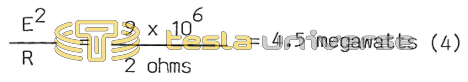
Power to the test wire was calculated as: