
TCBA Volume 13 - Issue 1
Page 5 of 18
A Homemade D.C. Powered Tesla Coil
Roger Smith
I have found that D.C. powered Tesla coils can be excellent performers and can offer some new options to the amateur who relies on surplus and scrap parts. The coil shown here uses two microwave oven power supply transformers with shunts removed - each driving a voltage doubler circuit of 8000 volts at 270 ma.
Originally, I used a bank of resistors totaling 60,000 ohms and got about 16 inches of spark. I then replaced them with a bank of inductors as described in Greg E. Leyh's paper (see Volume 10, #2) and got good results. The reactive ballast offers two benefits: (1) The reactor minimizes current flow while the spark gap is active and (2) the primary capacitor is charged to a higher voltage than the power supply voltage due to resonant rise (which Greg Leyh described very well).
With a coil such as this one, if the resonant rise effect is maximized, the following sequence will happen:
- Primary capacitor is charged to maximum voltage, current flow through the ballast is zero.
- Spark gap discharges. While oscillations occur in the primary, current flow through the ballast is low since it resists rapid changes of flow.
- Spark gap quenches, and current flow through the ballast starts to pick up.
- Current flow through ballast is at maximum when the multiplier output voltage and primary capacitor voltage are equal.
- Current flow through ballast starts to drop as the primary capacitor voltage continues to build.
- Current flow stops when primary capacitor voltage reaches twice the multiplier voltage. In reality, this value will be less due to resistance losses.
- Spark gap fires.
As with any coil, measures must be taken to protect the power supply from kick-back. The rectifiers seem to be the most sensitive component in the circuit. However, they should hold up fine once adequate measures are taken. For my coil, I employed RF chokes and filter capacitors in the circuit as shown in the circuit diagram (next page).
I also have one side of the primary circuit grounded through a capacitor (built into the primary circuit). The inductor closest to the coil on the ungrounded side of the primary circuit is immersed in oil to prevent arcing across the winding.
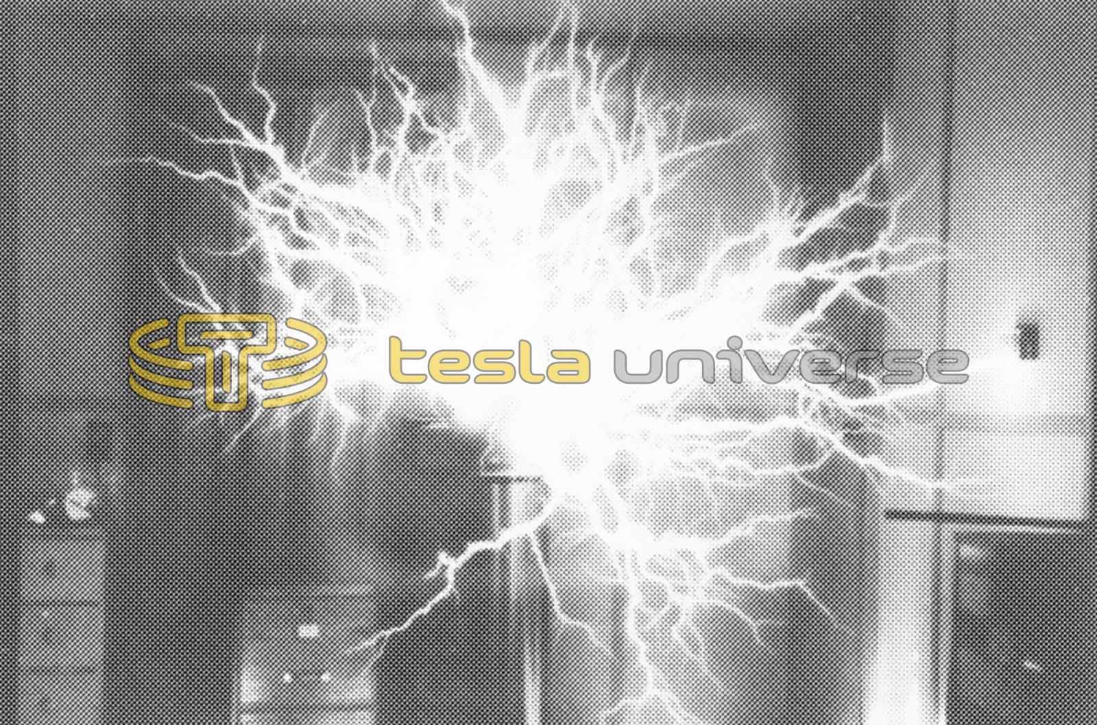
The spark gap system I use is a combination rotary and a multiple gap system. The use of a rotary with this coil is absolutely necessary. At the present time, this Tesla coil produces 42" point-to-point sparks with a 2200 VA input.
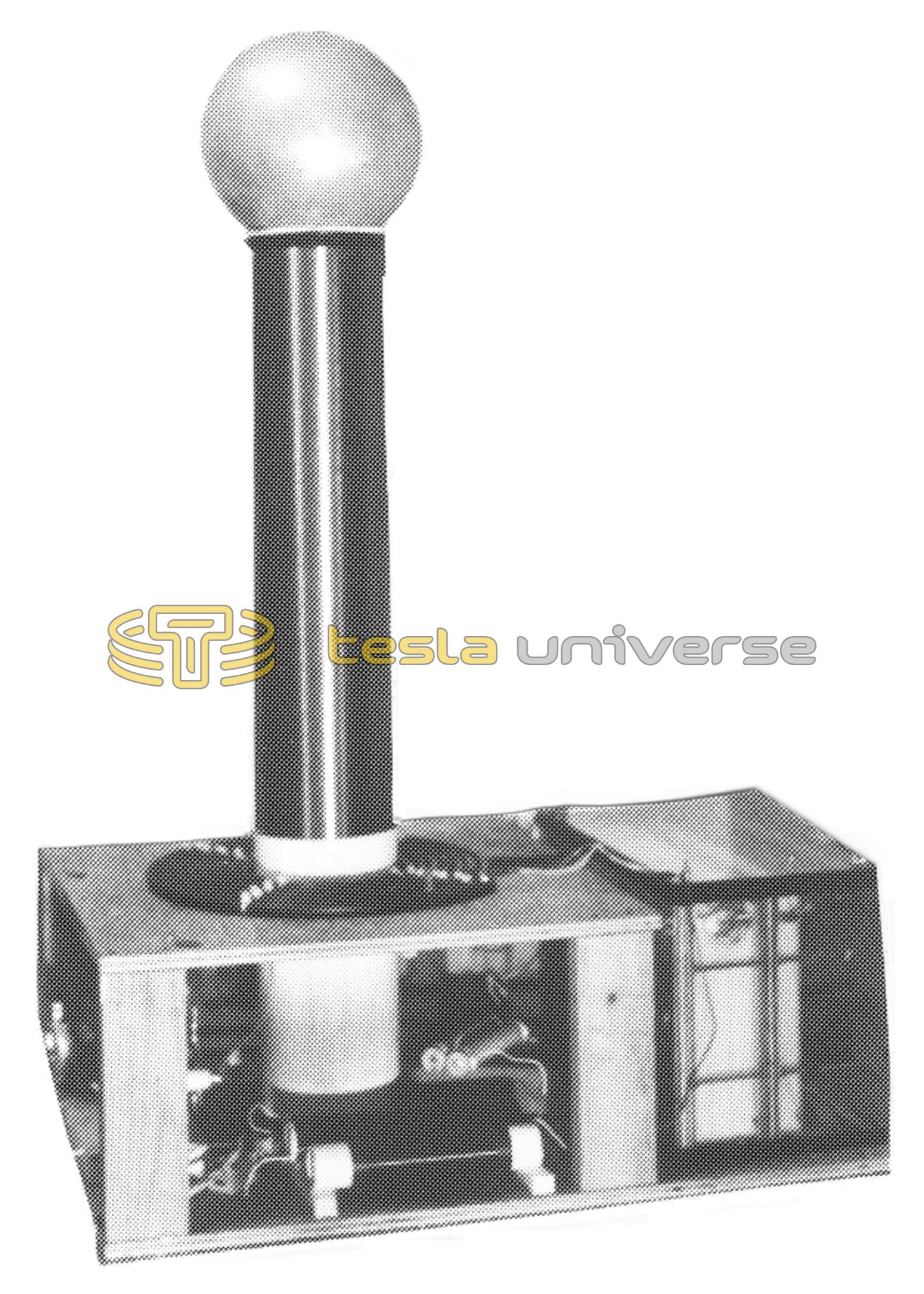
- Secondary - 900 turns of #22 gauge enamel coated wire close wound on a 6 5/8" diameter PVC pipe. The winding length is 26" and is topped with a 10" diam. sphere.
- Primary - A flat wound spiral with 8 turns of 5/8" aluminum coaxial cable, tapped at the 8th turn.
- Capacitor - 0.0275 uf homemade parallel plate type with 90 mil high density polyethylene as a dielectric. It is immersed in a fish tank filled with oil.