TCBA Volume 3 - Issue 1
Page 10 of 18
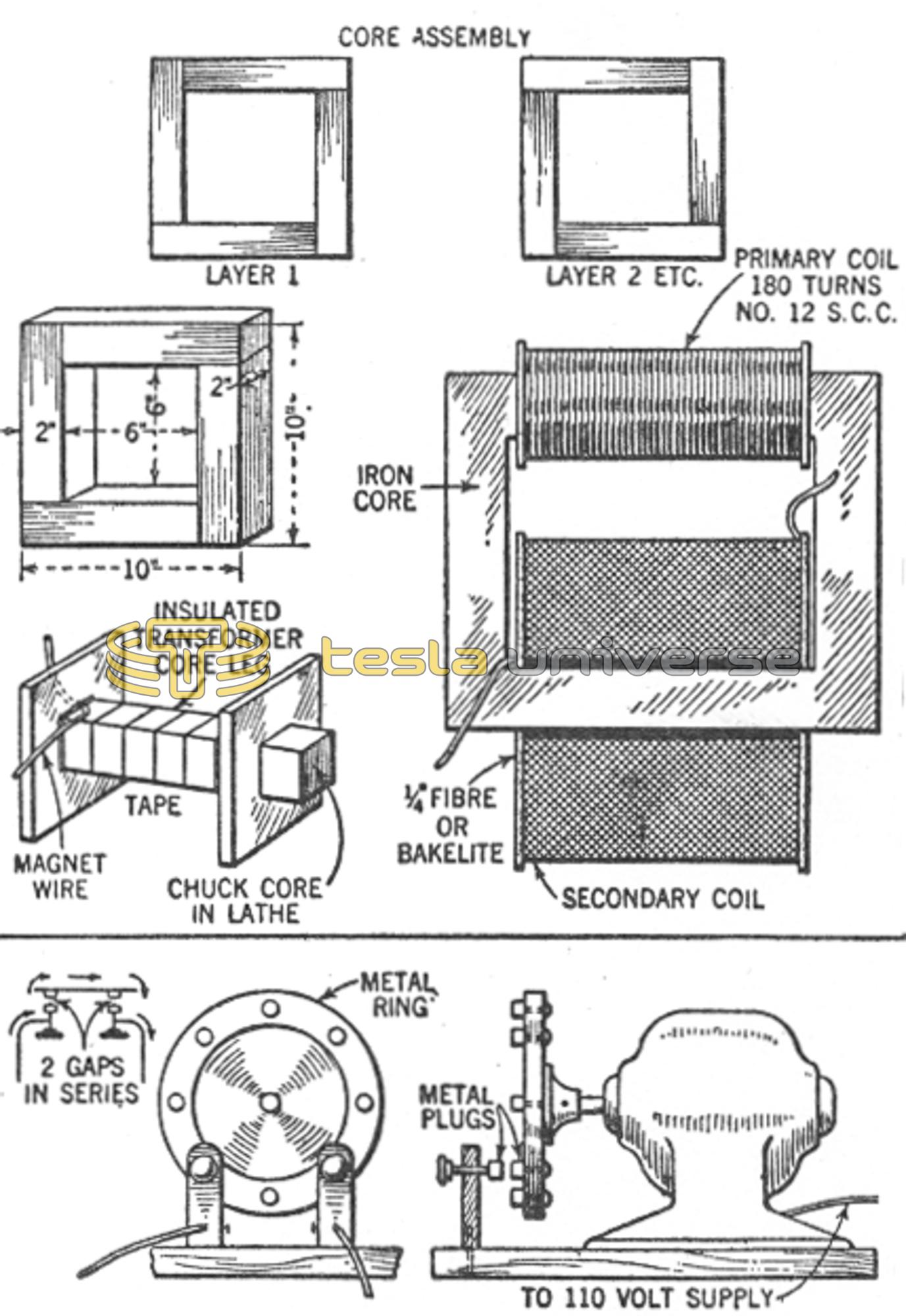
The secondary consists of approximately 36,000 turns of No. 34 enameled wire. The secondary must be very carefully wound and well insulated between layers. The layers do not need to be wound with machine accuracy, but can be wound 2 or 3 turns deep, if the winding steadily progresses across until a layer is completed. But never allow even one turn to throw back an inch or so over what has been wound, or a puncture between turns of several hundred volts difference in potential will result later.
Insulate each layer with a good sheet of .007-inch thick varnished cambric, and a layer of friction tape which is convenient to hold all the winding tight and compact. Do not wind the layers within 1/2-inch of end of insulation, or of end collar, so there will be no chance of any turns slipping down in the crack to other layer ends. Fill in that space on each layer with tape.
Connecting leads of heavier, flexible wire should be attached to the ends of the fine wire, and wrapped several times around the coil, to remove all strain from the fine wire. The inner lead must, of course, be attached at the start of the first layer, and should be brought out through small hole in the end collar, very well insulated from all layers. Do not try to bring this lead out inside the collar, next to the ends of all the layers of winding, or a puncture and short circuit will usually result. The secondary leads should also be attached to a fixed terminal strip. About 12 pounds of No. 34 wire, and 45 pounds of iron are required for this part.
The High-Voltage Condenser
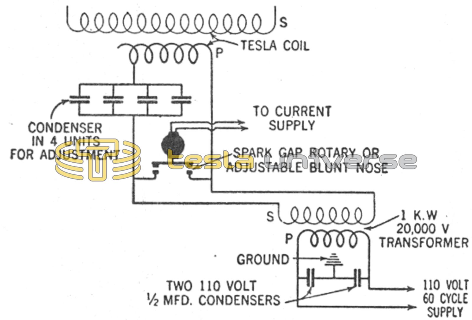
THE condensers can be built in three or four rubber or glass jars, to obtain flexibility or adjustment by connecting part or all of them in parallel. The totals should consist of 48 plates of thin sheet brass (.003-inch or .005-inch) thick and each 6 inches by 8 inches, or, if desired, a greater number of plates of smaller size, just so the total area is the same. Sheet brass was used in this condenser to eliminate part of the losses and heat obtained with tinfoil, and to make a more rugged condenser. The insulation consists of uniform double-strength glass plates at least 1/2-inch larger all around than the brass sheets, to prevent flash overs at the edges. Each group is tied and immersed in a jar of transformer oil. The finished condenser should be protected by a safety gap, of heavy wire pieces, set about 5/8-inch to 3/4-inch apart, at all times, to prevent breakdown of glass plates. Mica plates can be used in place of glass, if desired, and are a little thinner, but usually cost more.
How to “Tune” Circuits
The spark gap can best be a good rotary type, but very good results can also be obtained with a plain adjustable blunt-nosed gap, with careful adjustment. These adjustments are all very important to get best results, and should be tried experimentally until best values are found for any given coil.
It is also quite important in the operating of such equipment to have all the wires connecting the various parts as short as possible and quite large, No. 12 wire or over preferred. This is because the “skin effect” of high-frequency voltages is very pronounced, and causes considerable loss in even a few inches or feet of extra wire.
“Stunts” you can Perform
Care should be taken not to touch the leads of the 20,000-volt transformer or primary coil, as a burn might result.
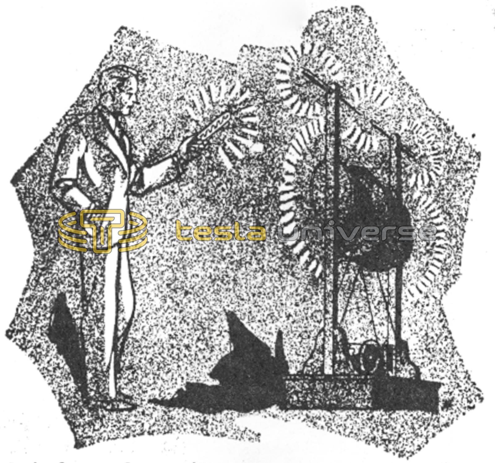
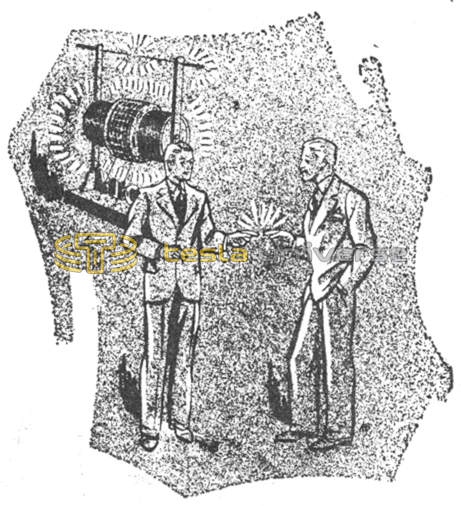
Geissler tubes will glow several feet from the coil in operation, when one end of such a tube is held in the hand. Beautiful violet discharges can be formed in a large lamp bulb with a good vacuum. Two small incandescent lamps can be lighted by their filaments, by two persons, each holding one in their hand, with thumb and finger on the brass bases, and touching the base centers together. One person should touch one terminal of the coil.
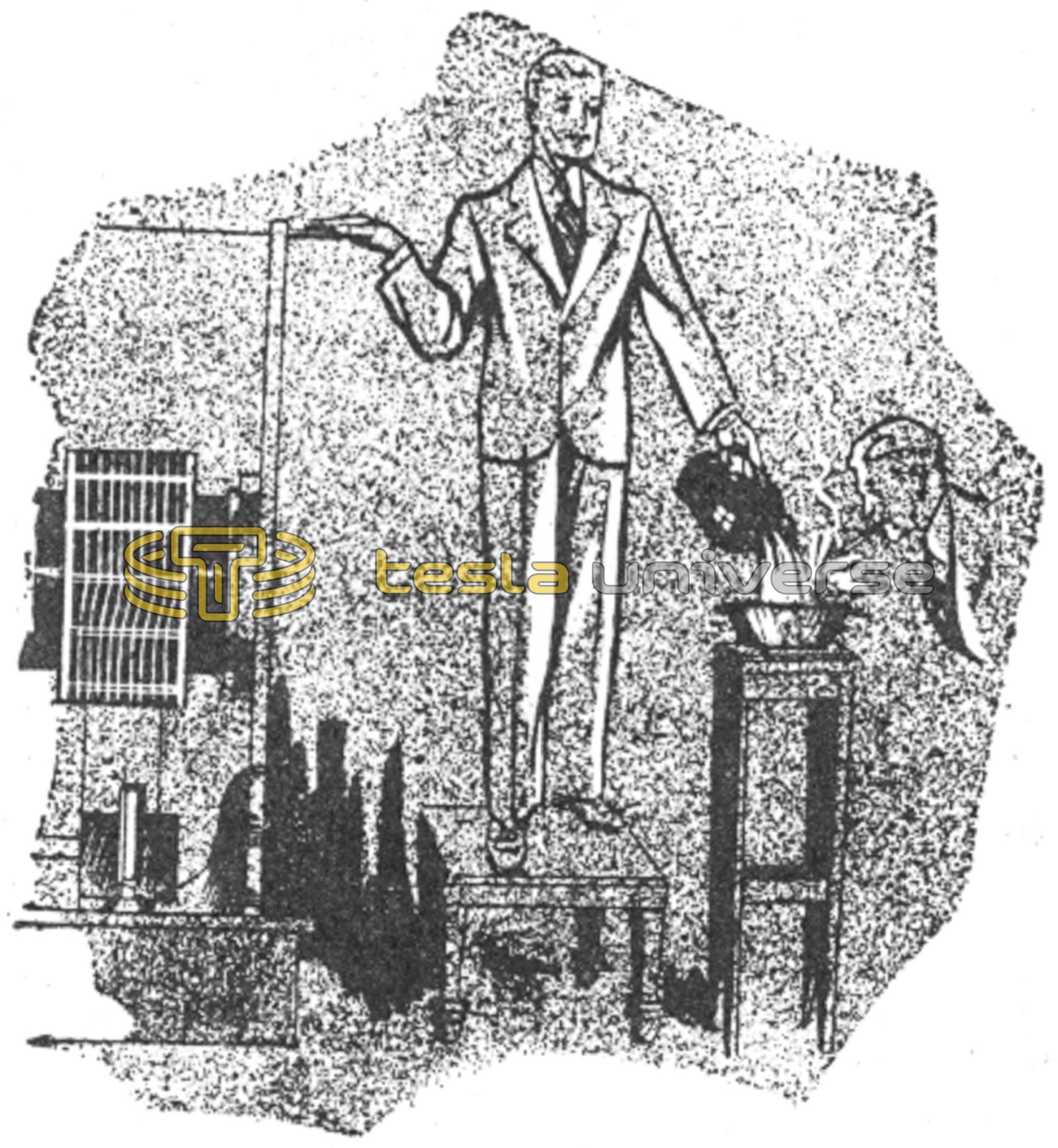
Another interesting experiment is to have one person stand on an insulated stool, make contact with one hand to a coil electrode, and pour a stream of water from an aluminum pitcher with the other, and into a pan on a second stool (not grounded). Another person can then light a cigarette from the stream of water. The cigarette can be prepared by running a fine wire through it to make contact to the person's hand, and the cigarette end moistened with alcohol or naphtha.