TCBA Volume 3 - Issue 1
Page 6 of 18
The Spark Gap
(continued)
The four types of gaps to be discussed in this series are the (1) plain gap, (2) multiple gap, (3) rotary gap, and (4) the quenched gap. This issue of TCBA NEWS will focus attention on the characteristics of the plain gap.
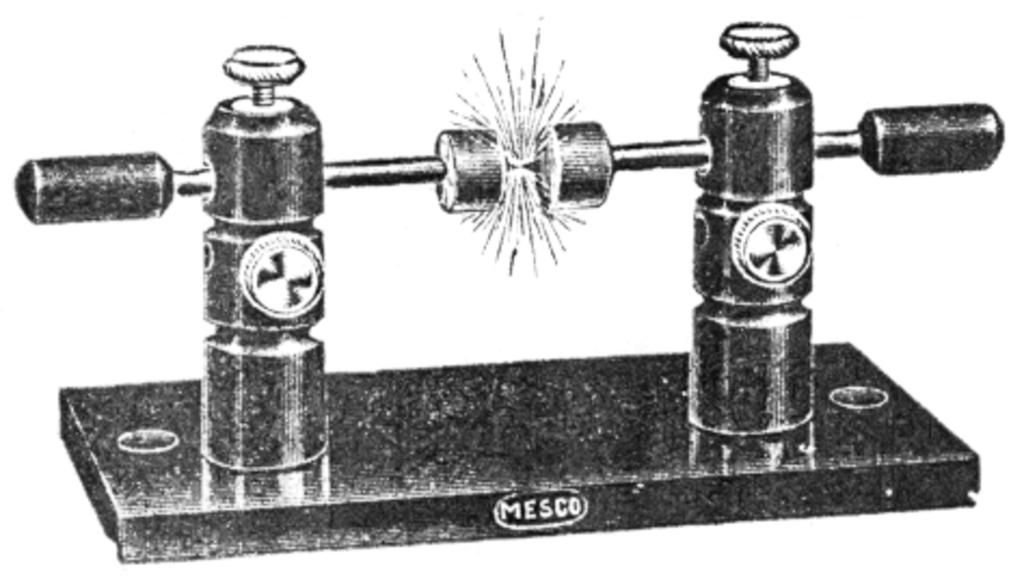
The plain or simple spark gap is made up of two opposing surfaces with a small space between them. The distances between the two sparking surfaces is determined by the circuit voltage. The higher the voltage, the greater is the distance. The sparking surfaces may be in the form of a sphere or flat blunt ends. Pointed spark gaps are not recommended in high frequency work. Two reasons why points are undesirable are (1) electricity jumps from points at lower voltages thus preventing the primary capacitor from reaching a full charge. (2) Points tend to remain ionized, a condition that hinders the return of the gap to a nonconducting condition.
The materials used in the gap may be made from zinc, brass, copper, or similar materials. The actual sparking surfaces should be as large as possible. It is recommended that they be no less than one-inch in diameter - larger, if possible.
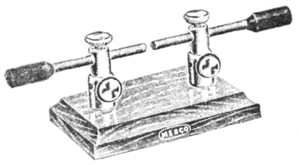
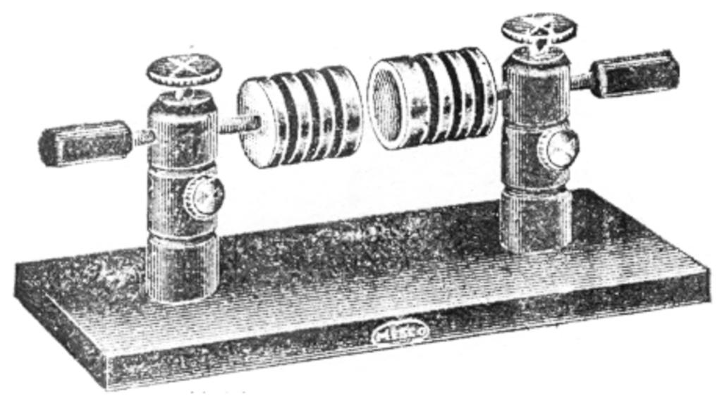
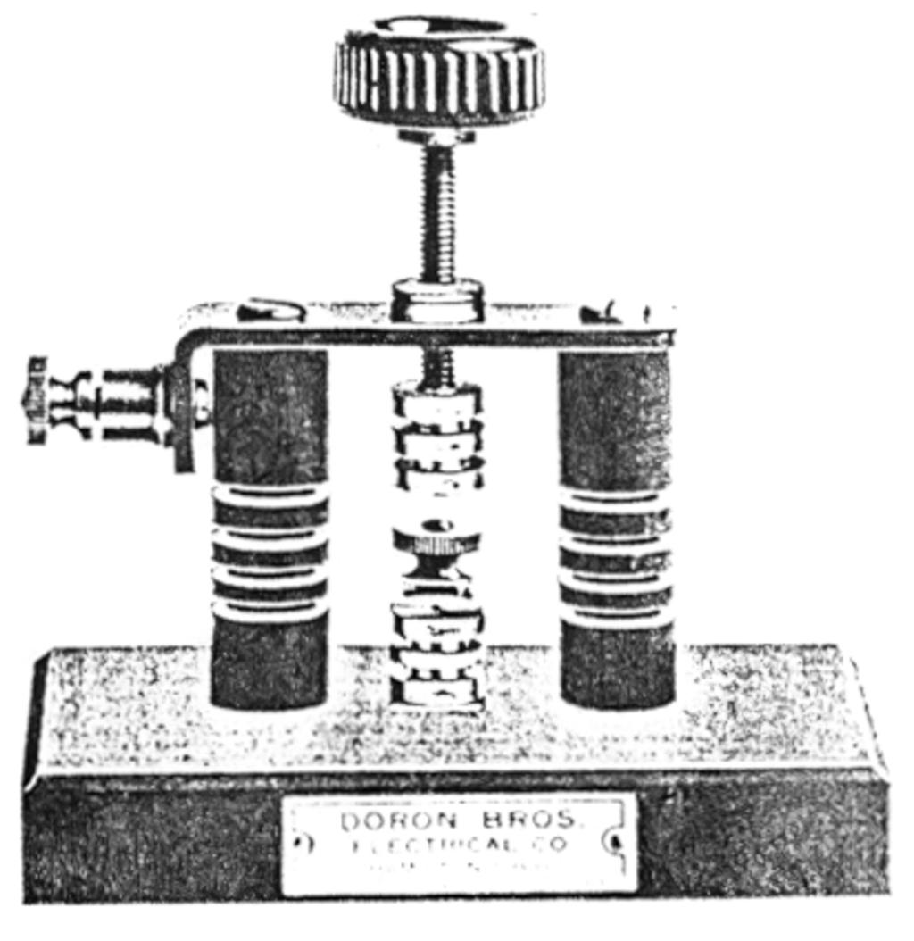
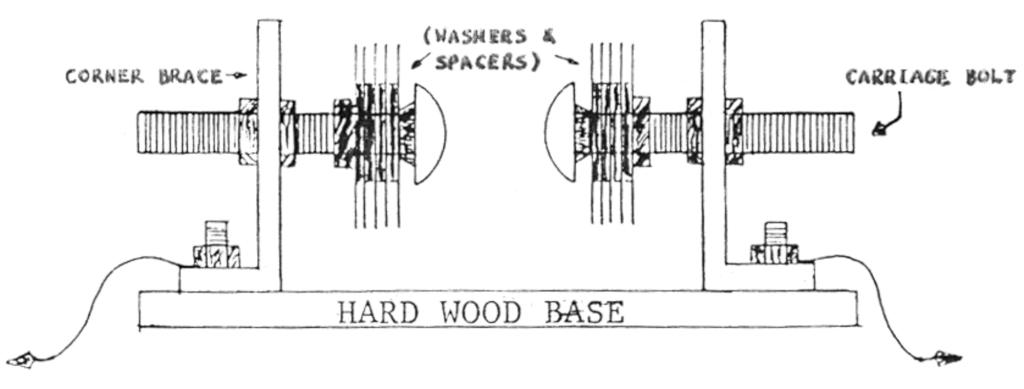
The best arguments for using the plain gap are (1) it is easy to construct and (2) can be made from readily available and inexpensive materials. However, it has a few drawbacks. (1) The space between the sparking surfaces is necessarily large that a strain is placed on both the power transformer and the primary capacitor. (2) A plain gap tends to overheat thus making it difficult to shut down or quench the initial spark. One method of improving its operation is to install a blower or reverse end of a vacuum cleaner near the gap. Another system for cooling the gap is to apply fins to the sparking materials. These tend to encourage convection currents. The following diagrams show the basic construction details of the plain spark gap.
(A HOME CONSTRUCTED GAP)

