
TCBA Volume 9 - Issue 1
Page 10 of 18
Frequency Shift Calculations
By
D.C. Cox
Introduction
Tesla oscillators contain LC “tank” circuits which consist of two separately tuned tanks: the primary circuit consisting of LpCp, and the secondary circuit consisting of LsCs. The secondary circuit achieves maximum energy when the primary and secondary circuit are tuned to the same frequency.
Common practice in Tesla coil design is to start by designing and winding a suitable secondary inductor which is tuned to the 1/4-wavelength of the frequency at which you wish your system to operate. The primary circuit is then adjusted and tuned to this operating frequency by adjusting either the primary inductance Lp, or the primary capacitance Cp.
While constructing experimental designs, it is often necessary to add either capacitance or inductance to the primary tuned circuit to shift its resonant frequency up or down to match the measured resonant frequency of the secondary inductor. This article presents information to precisely calculate the amount of inductance or capacitance necessary to shift the resonant frequency as required. These simple-to-use equations eliminate tedious Tom Edison style trial-and-error fiddling.
FIGURE 1 illustrates a Tesla oscillator circuit consisting of dual tuned circuits. The variables are as follows:
- Lp = primary inductance in Henries
- Cp = primary capacitance in Farads
- Ls = secondary inductance in Henries
- Cs = secondary capacitance in Farads
- Fp = resonant frequency in primary LC circuit in Hertz
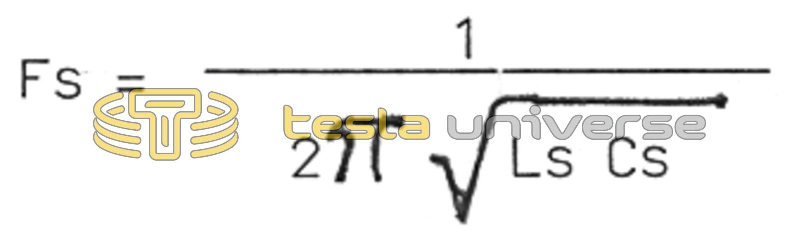
- Fs = resonant frequency of secondary LC circuit in Hertz
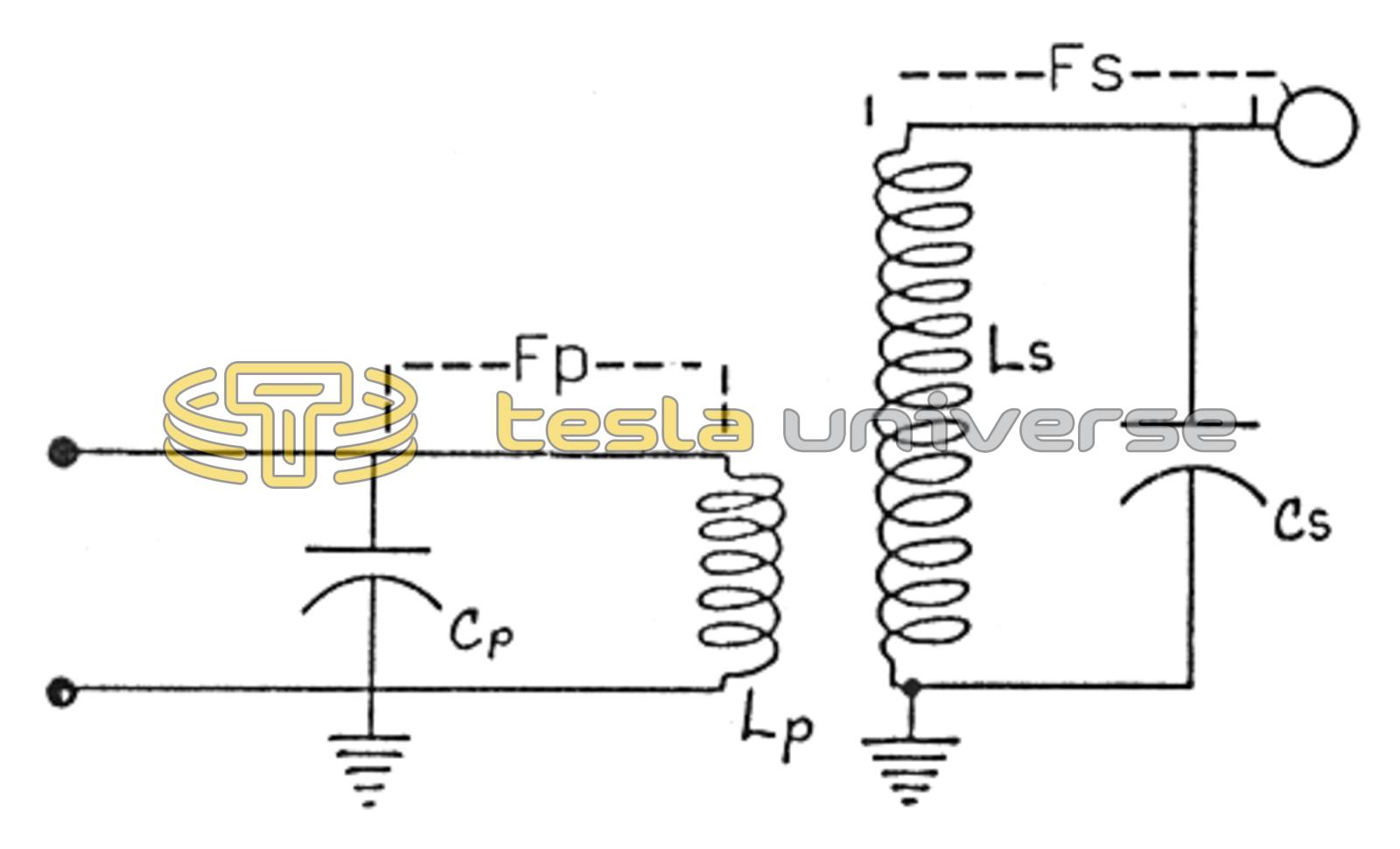
The traditional units of Farads and Henries are retained to eliminate confusing conversion factors so as to keep the equations straight forward as possible. The resonant frequency of the primary circuit is represented in equation 1 while the resonant frequency of the secondary circuit is represented in equation 2.

At resonance, the two frequencies should be equal, that is, Fp = Fs. So, at resonance, by transposing equations, equation 1 is equal to equation 2. Basic algebra enables us to derive the following equation 3.
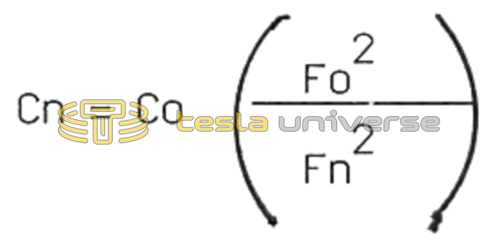
- Co = original or present capacitance in Farads
- Cn = new capacitance value required in Farads
- Fo = original frequency in Hertz
- Fn = the new or desired operating frequency in Hertz
Now, let's put it to practical use. Assume a resonant frequency of the secondary tank circuit, LsCs, to be 250 kHz. Now look at figure 1. After checking the resonant frequency of the primary circuit, LpCp, we find its measured frequency to be 290 kHz. To reduce the resonant frequency of the primary to be in tune with the resonant frequency of the secondary requires a frequency shift of 40 kHz. This requires adding capacitance or inductance to the primary circuit. For reasons which I will discuss later, it is preferable to add capacitance whenever practical. Entering these values into our equation results in the following equation 4.
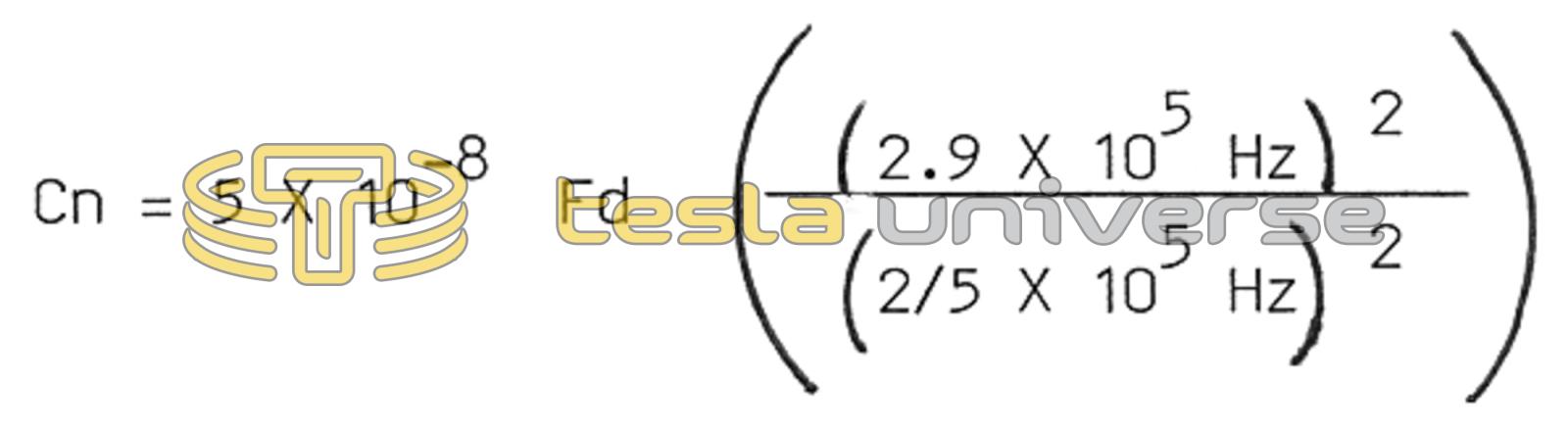
The same equation can also be used to shift the frequency up if required.