
TCBA Volume 9 - Issue 1
Page 9 of 18
Vacuum Tube Tesla Coil
Mike Martin, 710 Colorado Ave., Louisville, KY 40208
This coil is based on an article that appeared about 1960 in an issue of SCIENCE EXPERIMENTER magazine. I decided to build it breadboard style without the fancy Plexiglas box enclosure called for in the plans. Also, a few other changes were made to improve performance.
The original design used a 4" outside diameter primary coil form and a 2" O.D. secondary with a winding length of 17 3/4" wound with #32 ga. enameled wire.
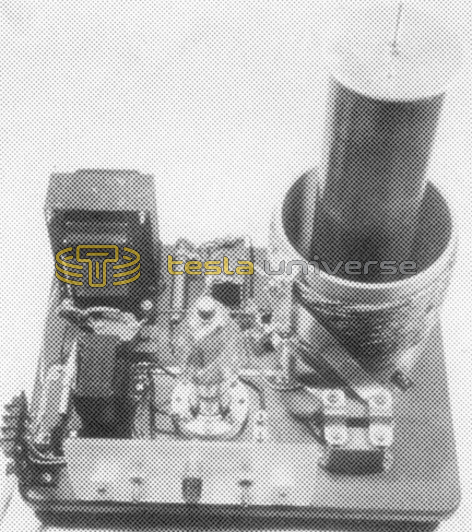
This was replaced by a section of 3 1/2" O.D. PVC pipe wound with 29 ga. cotton/enamel magnet wire for a winding length of 10 3/4". The pipe ends were fitted with 3/8" Plexiglas disks and the secondary winding was terminated with a 1/8" aluminum disk slightly larger than the coil O.C. A 1/4" brass rod is threaded into the center of the disk for the discharge terminal. The finished secondary was given three coats of red Glyptal.
The primary coil is 15 turns of cable formed from six strands of 20 ga. plastic insulated telephone switchboard wire twisted together and wound on a 6 1/4" O.D. PVC form. The grid coil is 18 turns of 24 ga. enameled wire wound on the bottom end of the form near the primary. The windings were given several heavy coats of PVC cement to hold them in place.
The triode tube specified in the original plans is a 5514, a tube that was probably already obsolete even in the early 1960's. I just happened to have one and also the proper filament transformer so I went ahead and used it. An 811-A or any similar triode would work with the proper filament voltage and grid resistance.
I used a 2500 ohm 50W adjustable resistor in the grid circuit. Probably a 100 watt would have been a better choice since it gets very hot but not enough to be a serious problem.
The circuit is resonant at approximately 500 kHz with two .001 mfd, 6 kv mica capacitors in parallel across the primary.
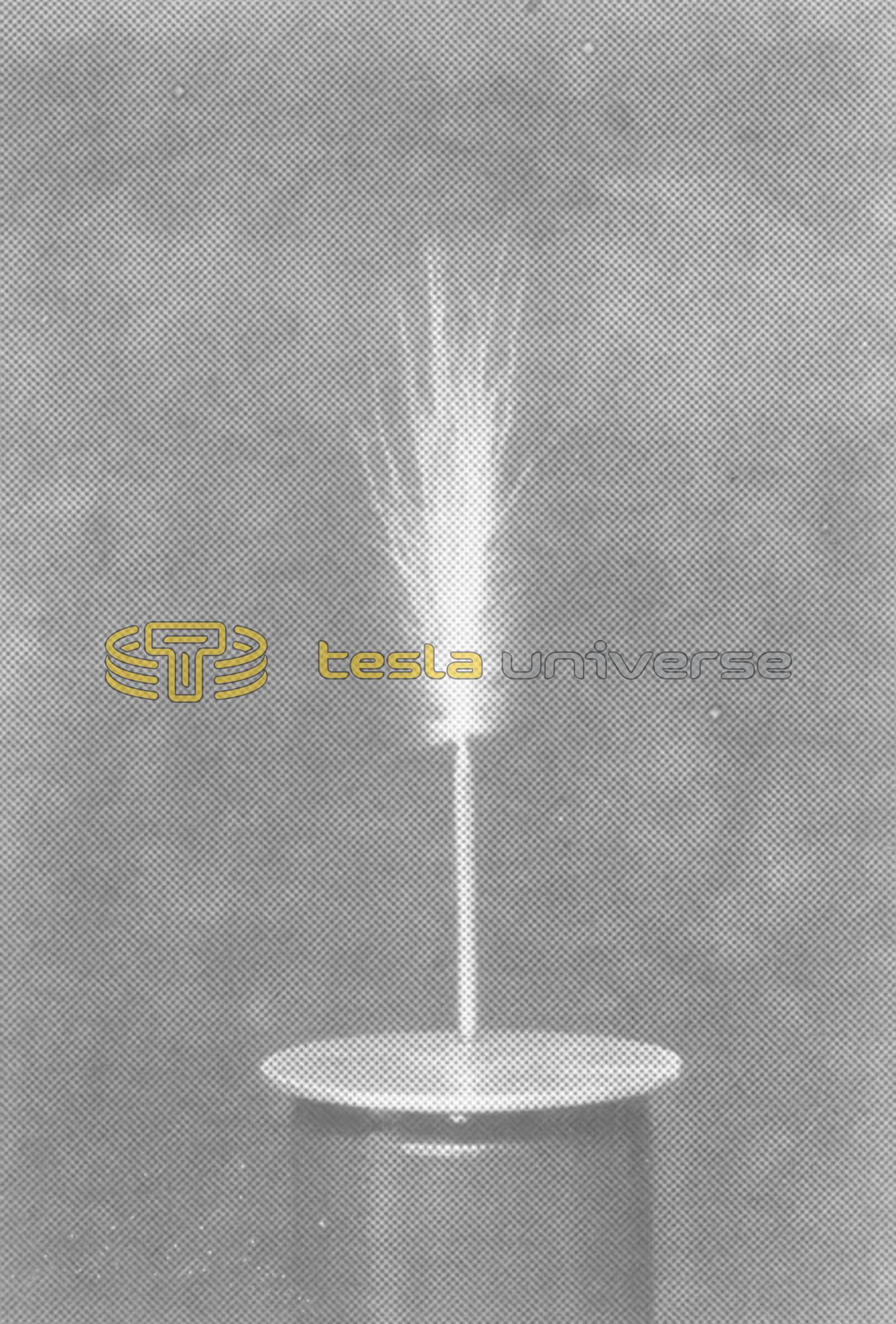
The finished coil gives a 6" discharge with 1200 volts on the plate.
The photo of the discharge was taken on ASA 400 sheet film with an aperture setting of f/9 at 1/2 second. A second exposure was made with a flash unit to show the coil itself. Otherwise, all that you would have seen is the discharge.