TCBA Volume 9 - Issue 1
Page 11 of 18
Practical Considerations
Most Tesla oscillator systems consist of 3-5 turns of copper tubing which is the preferred material as copper ribbon has a sharp edge which tends to disrupt the electrostatic field near the secondary inductor. This disruption usually results in corona formation which stresses the field. Continuous operation in this mode will deteriorate the insulation on the secondary inductor.
Most small and medium-sized systems should limit the primary inductor to 5 turns or less. This keeps the inductance ratio (notice I said inductance ratio, not turns ratio) high to maintain high voltage multiplication. This requires adding capacitance or substracting inductrance from the primary system if maximum performance is to be achieved.
Practical considerations such as manufactured standard values for capacitors and our personal budgets may dictate adding or reducing inductance slightly to bring the system into resonance. This works well as long as no less than 2 turns or no more than 5 turns are incorporated in the primary inductor.
Keeping these practical considerations in mind, we can modify the capacitance frequency shift equation to also be used to calculate inductive frequency shift as shown in equation 5.
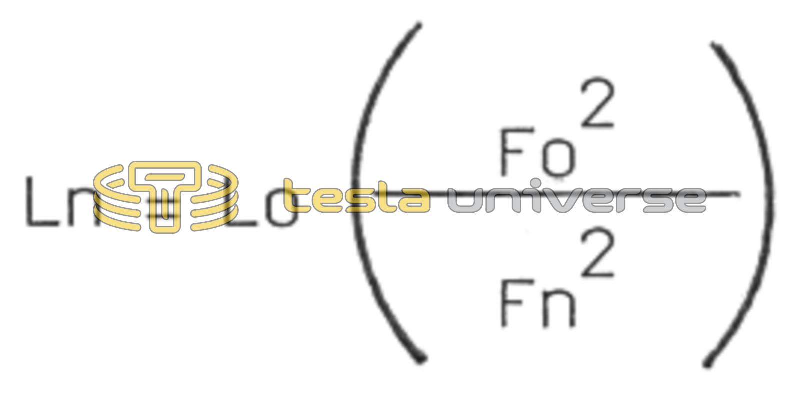
- Ln = new inductance value required in Henries
- Lo = original or present inductance in Henries
Standard practice is to use this equation in combination with a hand-held digital inductance meter to shift the inductance (and, hence, primary frequency) up or down as required to match the secondary circuit resonant frequency.
SUMMARY
Try to keep your primary turns in the 3-5 turn range. It is usually best to add capacitance, not inductance, to achieve the required frequency shift. The more capacitance, the more energy (and usually current) flowing in the primary circuit. More powerful currents produce more powerful magnetic fields which link the primary-secondary circuits.
Two eguations are presented which enable quick and accurate calculation of inductance and capacitance values required for a specific frequency shift. These simple equations combined with an inexpensive measuring device allow the Tesla coil designer to quickly test and evaluate both new and previous system designs.
D.C. COX
Resonance Research
E11870 Shadylane Rd.
Baraboo, WI 53913