TCBA Volume 9 - Issue 1
Page 14 of 18
Spark Gap
The spark gap is an automatic switch. Its purpose is to connect the charged capacitor to the primary coil at the proper time. The conducting path through the switch is the ionized air between the electrodes. The adjustment of the distance between the electrodes, the shape of the electrodes, their operating temperature, how clean they are, and how much air is blowing across them sets the spark gap firing threshold. Opening up the gap to the maximum distance where satisfactory operation may still be obtained insures maximum efficiency. However, adjustment at this point also places the greatest voltage stress on the components. The power transformer is the most susceptable component for failure and will no doubt be the first thing to go. Keeping the gap set below the maximum point is nearly impossible for any true “mad scientist,” but will extend transformer life.
The spark gap electrodes are Miller TIG welder 'points' P.M. 020-603. They consist of 3/8 diameter tungsten material welded to a short length of 1/2" diameter rod, 3/4" diameter by 1" long aluminum alloy round stock.
The aluminum holders have been machined to accept the electrodes and position them on top of the 3/4" diameter pillar in line with the quench fan draft.
The purpose of the high volume 5" muffin fan is to extinguish or quench the spark once the energy transfers from C1 to L1. A poorly quenched spark results in a dampening effect on the oscillations that occur in L2 and therefore limits the discharge spark length. The fan draft is brought into varying degrees of alignment with the spark gap as required by means of a pivoted corner and locking slide.
Transformer Protection
RFCa and RFCb, and C2a and C2b are designed to prevent most of the radio frequency high voltage generated at the spark gap from appearing at the power transformer output terminals. This high voltage, if not attenuated, would puncture the transformer insulation and cause permanent failure. The purpose of the wide spaced turns at the capacitor end of RFC1 is to reduce the distributed capacitance and increase the turn-to-turn breakdown threshold where most of the high voltage attenuation takes place. The safety gap helps to protect the power transformer from the RF high voltages that may get through the RF choke. When these voltages do get through the choke, the safety gap when properly adjusted fires and shorts them out. This action also shorts out the power transformer output but the transformer can withstand output shorts. It cannot withstand insulation punctures.
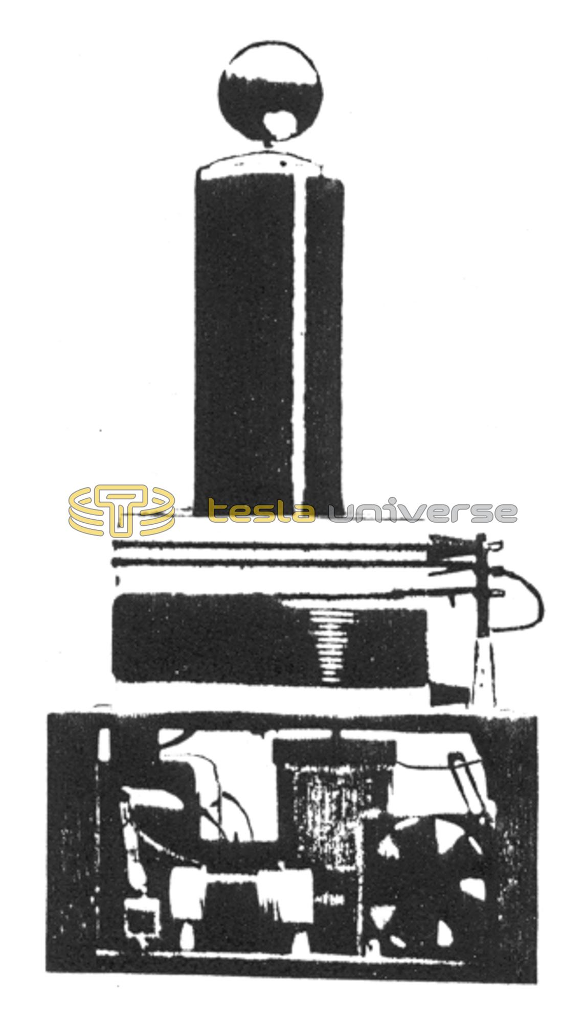
Operation
When the main spark gaps are adjusted to 5/32" spacing and the coefficient of coupling is set with the three secondary sleeve screws in holes #4, the coil will produce a 18 to 21.5" discharge with about 400 Watts input power. The approximate secondary frequency with no discharge electrode is 240 kHz. A 4 1/2" sphere reduces the resonant frequency to 220 kHz while a 9" pie pan becomes 210 kHz. Maximum discharge occured with the primary tap set at the 14th turn.
I will be happy to discuss this project with anyone interested in building one.