
TCBA Volume 9 - Issue 1
Page 8 of 18
High-Frequency Experiments
Operating An Oudin Coil From a Vacuum-Tube Oscillator
By H. Winfield Secor
• MANY experimenters have built Tesla and Oudin high-frequency coils which they have operated either with mechanical vibrators or else with a spark gap and condenser arrangement, in a manner well known to the electrical fraternity.
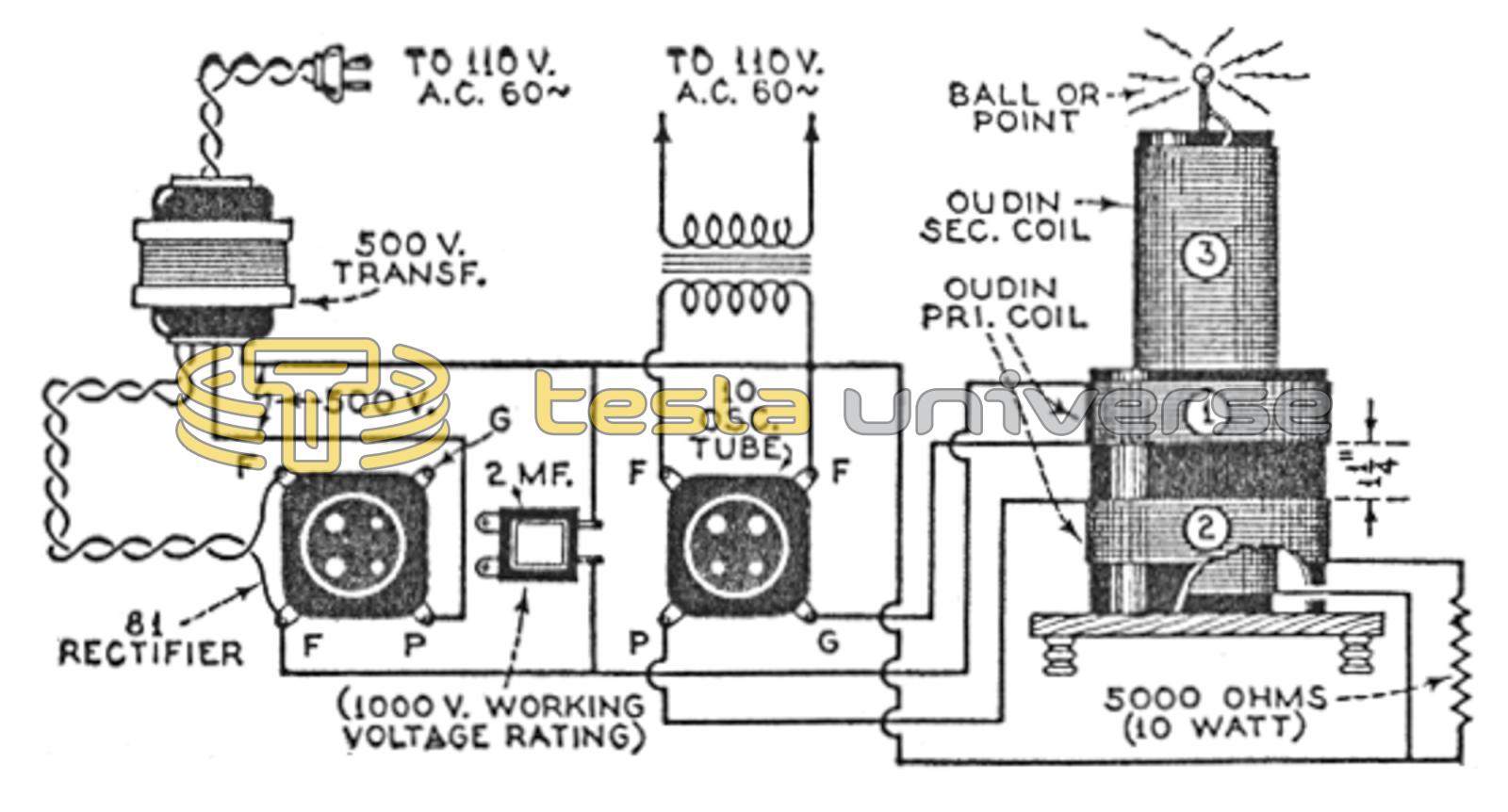
Today, however, when vacuum tubes are applied to a hundred and one different problems, the experimenter is anxious to know, undoubtedly, how he can operate a high-frequency coil, such as the Oudin, by means of a vacuum-tube oscillator. In the diagram below (Fig. 1), there is shown one of the simplest methods for accomplishing this result. The apparatus required is simple and of nominal cost and, in many cases, the parts can be found in the surplus stock of the home radio laboratory.
For constructing the high-frequency apparatus illustrated in Fig. 1 we need a 500-volt transformer, with a primary winding designed to operate from the usual 110-volt, 60-cycle A.C. lighting circuit.
Next we need a pair of tube sockets, a radio tube of the 210 type, and also a half-wave rectifier tube such as the 281. Across the rectifier there is placed a 2-microfarad condenser, rated at a working average of 1,000 to 1,200 volts.
The high-frequency coil comprises two primary windings (1 and 2); each composed of 20 turns of No. 16 D.C.C. magnet wire wound on a 4-inch (diameter) form or tube. The two coils are spaced about 1 1/4" apart. The secondary winding (3) is composed of about 750 to 800 turns of No. 28 D.C.C. magnet wire wound on a 2 3/4" diameter tube. To obtain the longest high-frequency sparks from the free end of the secondary at “A”, the turns of No. 28 wire should be spaced the thickness of the wire apart, for better insulation. In any event, the turns of wire at the high-voltage end of the Oudin secondary coil (3) should be spaced, to improve the insulation and prevent break-down due to the high electrical stress between the turns. Note that the 210 power tube, which serves as the oscillator, has its filament current supplied by a 7 1/2-volt winding, on a separate filament transformer, unless this winding is a part of the 500-volt transformer. A 5,000-ohm resistor, rated at 10 watts, is used in series with the grid coil.
Sparks an inch or so in length may be drawn from the Oudin secondary, whenever it is working correctly. If longer sparks are desired, larger power tubes should be used and also a higher voltage applied to the plate of the tube. A correspondingly larger size of Oudin coil should likewise be used, to carry the heavier current and voltage.
An oscillator using a 210 tube, which is quite common, having been used extensively in the power stages of broadcast sets at one time.
A higher-power set up for the Oudin coil, using a transmitting type tube. Better insulation and more care is needed in its construction and operation.
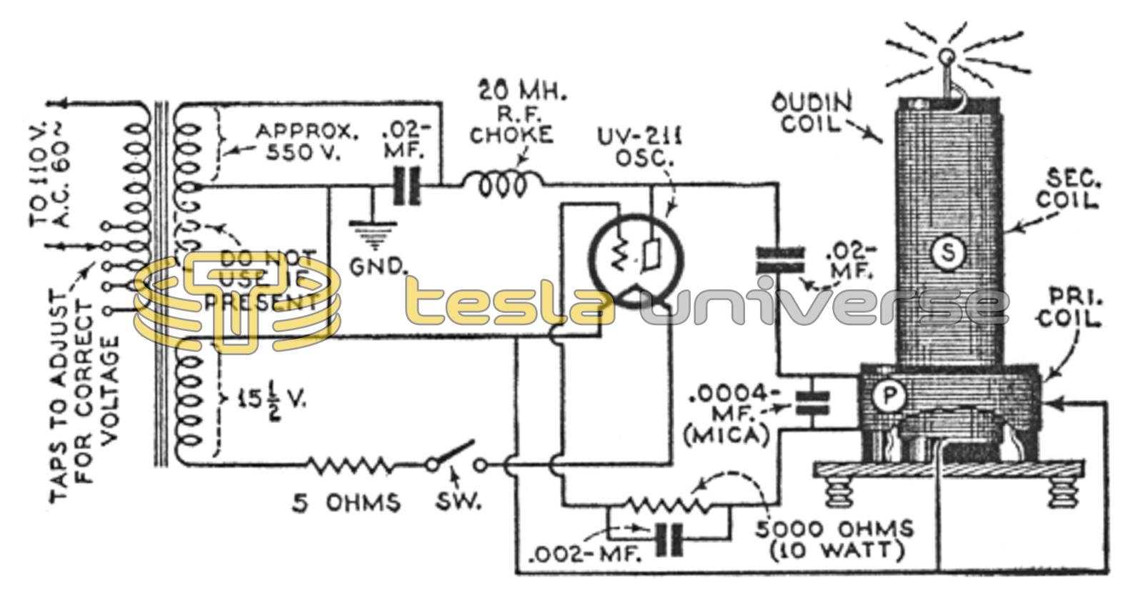
The diagram in Fig. 2, shows the line-up of a vacuum-tube oscillator and high-frequency coil of the Oudin type, supplied through the courtesy of one of the engineers of the General Electric Company. In this circuit a power transformer is utilized to apply 550 volts to the plate of the oscillator tube, which is of the UV211 (50-watt) type. Note that the two 7.8-volt filament wirings are connected in series, to supply the necessary voltage for the 211 tube (or a single 15-5-volt winding may be used) with a 5-ohm resistor in series, as shown in the diagram.
While it is hardly necessary to point out the fact to a radio amateur, the harmonics of this apparatus are capable of causing radio broadcast interference, and it should be operated with this fact in mind. In addition, it would be well to put a filter across the primary of the power transformer, consisting of two 1-mf., 300-volt condensers in series, with the common terminal between them well grounded. This will keep radio-frequency current from backing up into the power line.