
TCBA Volume 12 - Issue 1
Page 10 of 18
Recognition of a Series Resonant Circuit
Duane A. Bylund, 2581 Cherry Grove Way, S. Jordan, Utah 84065
One of the biggest problems that may exist with understanding how a Tesla coil works is that of recognizing the difference between a series and a parallel circuit. As an example of this, refer to the basic capacitive discharge Tesla coil which is shown in figure 1. The charging source for the primary capacitor is not shown for clarity. The secondary coil is shown with its effective capacitance.
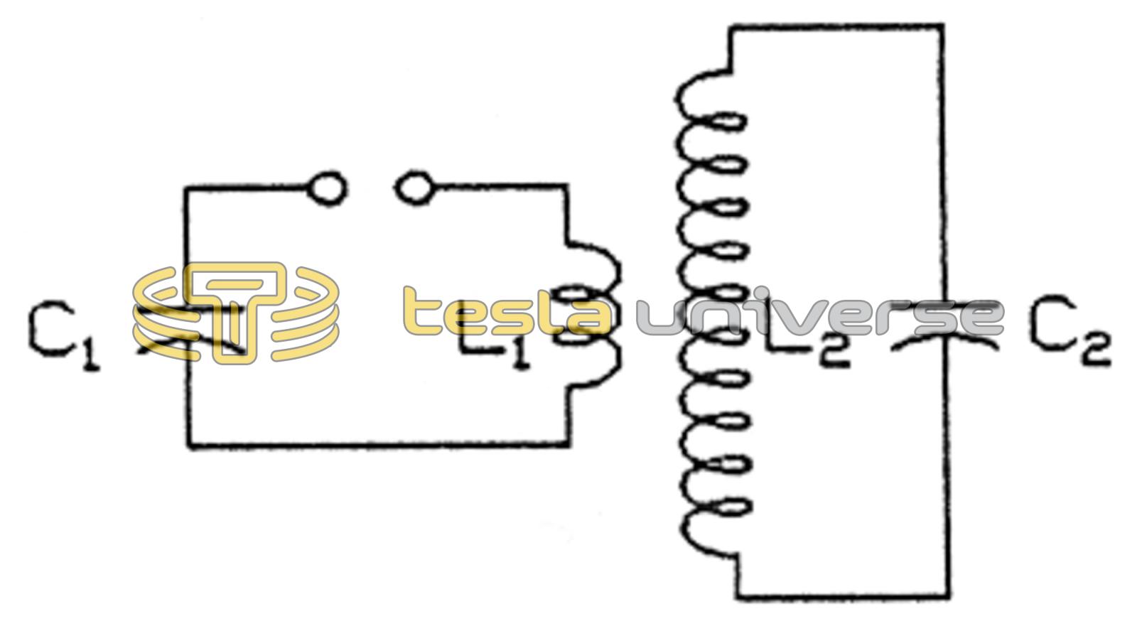
Are the two circuits, the primary, C1 and L1, and the secondary, C2 and L2, respectively, series or parallel circuits? At first glance, it would appear that they are both parallel circuits but a closer examination will reveal that they are both series circuits.
The main factor that determines if a circuit is parallel or series is where the source of voltage originates. If the source originates from within the circuit, then the circuit is considered a series circuit. In the case of the primary circuit, the capacitor is the source of voltage and there is only one path for current to flow. Thus, the circuit is a series circuit. As far as the primary circuit is concerned, energy that is transferred to the secondary coil is lost as heat and this may be represented as a resistance in series with the capacitor and inductor. When no definite source of voltage, such as a generator, etc., is shown inside the circuit, such as the secondary circuit, then the source of voltage is said to be internal and this makes the secondary circuit a series circuit. There is only one path for current to flow.
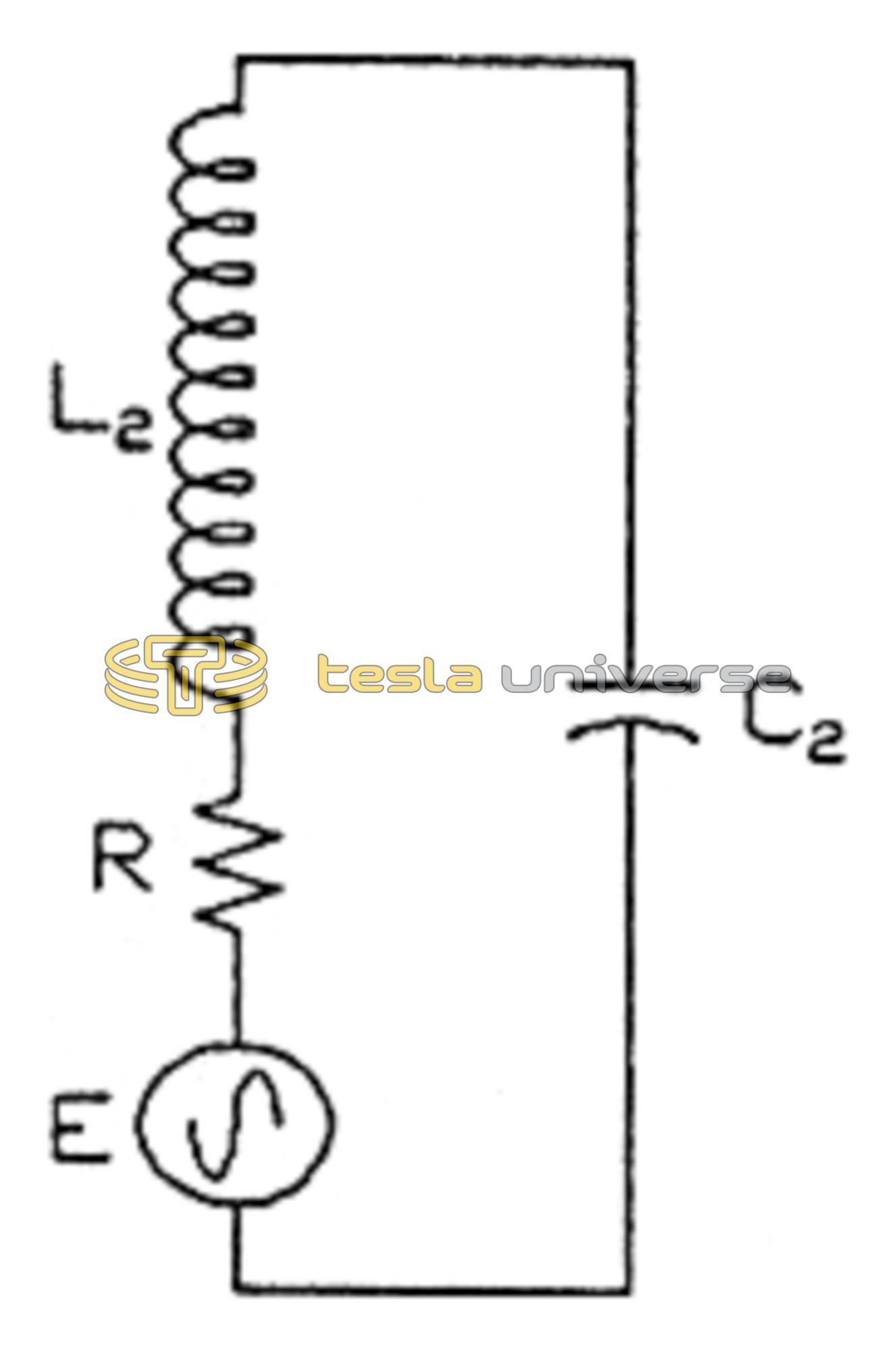
The capacitive discharge Tesla coil of figure 1 can be shown in its equivalent form of figure 2. The source of voltage in figure 2 is a function of the primary capacitor and its charge, the primary inductor, and the coupling between the primary and the secondary. The resistance is a function of the various losses. Recognizing the fact that the secondary circuit is a series RLC circuit is very important as it helps explain many things. For one, it is clear from figure 2 that direct coupling a source of alternating current to the base of the secondary coil will give the same results as inductive coupling. The net result is the same in each case of coupling! A Tesla coil is basically just a series resonant circuit being driven with a source of alternating current. It is also evident from figure 2 that the output voltage is directly proportional to the current in the base of the coil. That is, doubling the current in the coil will double the output voltage. Knowing this helps us determine what the output voltage is just by measuring the current in the base of the coil (which is a low impedance point), instead of trying to measure, and thus load, the output voltage at the top of the coil (which is a high impedance point).
Tesla knew that he was dealing with a series circuit at the very first of his experiments with resonant coils in 1891 and 1892. I quote some remarks here from his lecture delivered before the Franklin Institute in February, 1893.
“The magnitude of the resonance effect depends, under otherwise equal conditions, on the quantity of electricity set in motion or on the strength of the current driven through the circuit. But the circuit opposes the passage of the currents by reason of its impedance and therefore, to secure the best action it is necessary to reduce the impedance to a minimum. It is impossible to overcome it entirely, but merely in part, for the ohmic resistance cannot be overcome. But when the frequency of the impulses is very great, the flow of the current is practically determined by self-induction. Now self-induction can be overcome by combining it with capacity. If the relation between these is such, that at the frequency used they annul each other, that is, have such values as to satisfy the condition of resonance, and the greatest quantity of electricity is made to flow through the external circuit, then the best result is obtained. It is simpler and safer to join the condenser in series with the self-induction.
“By taking a coil with a very large self-induction the critical capacity is reduced to a very small value, and the capacity of the coil itself may be sufficient. It is easy, especially by observing certain artifices, to wind a coil through which the impedance will be reduced to the value of the ohmic resistance only; and for any coil there is, of course, a frequency at which the maximum current will be made to pass through the coil.