
TCBA Volume 12 - Issue 1
Page 15 of 18
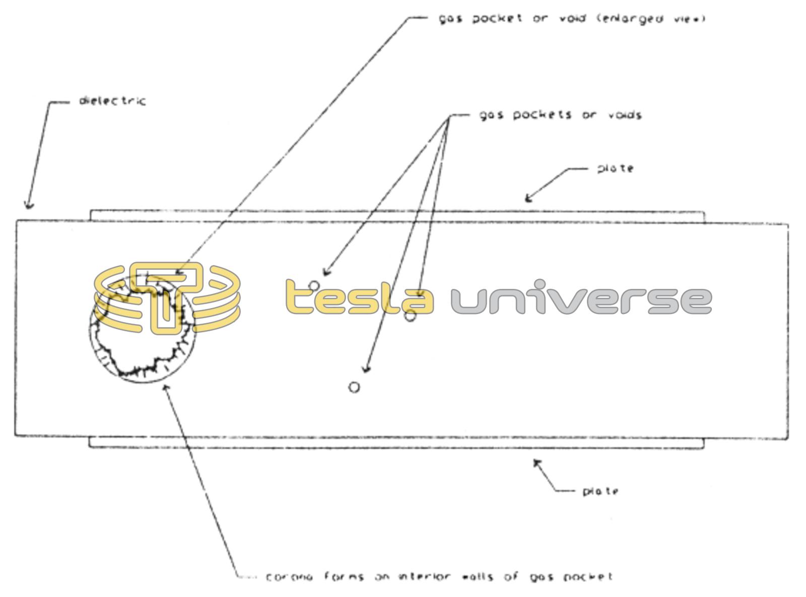
The gas pocket usually contains air which has a different dielectric constant than the surrounding material. The ionization threshold of air is usually considerably less than the value of the surrounding solid dielectric. Under high values of dielectric polarization and electric stress, an internal corona produces local heat buildup of the dielectric.
There are two ways to reduce gas pocket ionization failure. The first choice is to use a thin piece of low dielectric constant insulation. This is why polyethylene, polypropylene, mylar, PTFE (polytetrafluoroethylene, ie, Teflon), polystyrene, and Kovenex are favored over glass and other materials of high dielectric constant.
Capacitance varies with both the area and thickness of the dielectric. Capacitance varies inversely with the thickness of the dielectric. The expression for capacitance is:
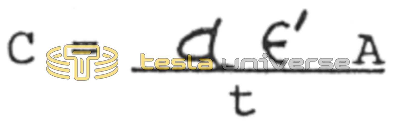
where

Another method of avoiding gas pocket ionization is to use as thin a dielectric material as possible. Typical production film thicknesses for mylar is .15 mils (.0015) inch. Insulating materials this thin cannot be handled by human hands without producing wrinkles which will lead to voids and seams in the dielectric. Special (and expensive) foil-handling and foil-slitting machines are used to handle both insulating materials and the thin copper foils used as plate material. Small demand for special foil-handling machines make them too expensive for the average capacitor builder. The slightest wrinkle in either the plate or dielectric foil would produce trapped air bubbles that might not be evacuated completely with vacuum pumping equipment. Again, corona would form in these voids and produce thermal damage to the dielectric.
The volume of a capacitor is: V = At where A is the area of the dielectric and t is the thickness of the dielectric. The ratio of capacitance to volume is found to be:
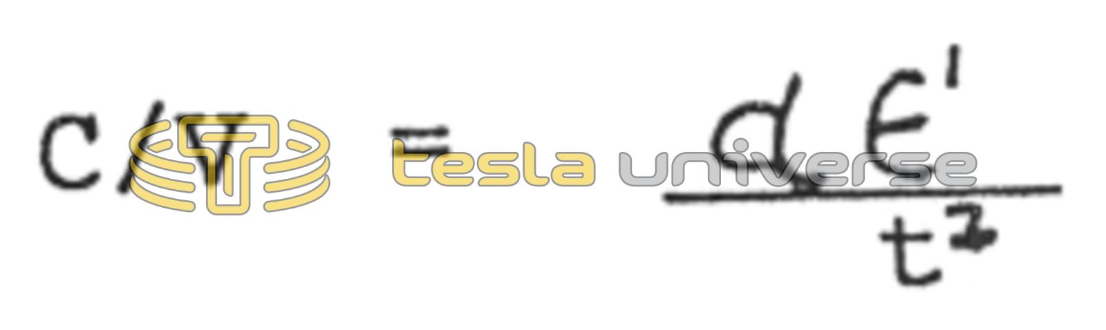
This ratio is a measure of the efficient use of a dielectric film, and since it varies as the inverse of the square of the dielectric thickness, it is of great practical importance to make t (thickness) as small as possible. The limit is governed by the physical strength of the dielectric film and the dielectric breakdown strength required of it. Optimum performance requires a series of thin dielectric units connected in series to achieve the required potential difference of the circuit under operation.
The last characteristic to be considered is the electrical dissipation factor. This is defined as the ratio of energy dissipated as heat to the energy stored in the capacitor when an alternating field is impressed upon it. The expression for the entire capacitor is: DF = ωRsC + 1/ωRpC
Where ω is an angular frequency (2πf), Rs is series resistance, ie, conductor loss. Rp is parallel resistance or dissipation within the dielectric itself, and C is capacitance. To evaluate the dielectric, it is measured in a capacitance cell which has thick lossless electrodes so that Rs becomes zero, and then DF = 1/ωRpC = G/ωC
The final equation for dissipation factor, DF, is simply the ratio of conductance to reactance of the capacitor. A favorable value, again, requires a thin dielectric material.
The average experimenter can construct efficient capacitors out of 1/8 inch thick sheets of polyethylene, polystyrene, Kovenex, etc.. However the reliability and useful life of these relatively thick dielectrics would prohibit their use for commercial or museum applications. Failure of thick dielectric capacitors usually occurs at less than 50 operational hours as compared with over 50,000 hours (MTBF) for commercial thin-film energy discharge capacitors.