TCBA Volume 17 - Issue 1
Page 12 of 18
As can be seen, this is a DC powered system and thus, a lot of precautions must be taken around the finished system as the DC voltage can easily kill instantly should the experimenter contact any of the primary circuit components. Three DC power supplies are required. The 30 volt and 12 volt supplies need supply no more than 100 milliamperes (.1 amp). The high voltage DC supply can be made up from a 5 or 10 amp variac controlled 60 ma neon sign transformer with a HV full wave bridge rectifier and moderate .05ufd or larger filter cap at the rated peak voltage of the system, (can be old paper type.). Typical current demands on the high voltage supply are on the order of 50ma in a small system. The experimenter can substitute different parts than called for in the diagram in order to “beef up” the output, increase the rep rate and expand on this basic design. The circuit shown is not a critical one on the “edge of operation”, but a core level foundation using techniques which were modern 50 years ago. To my knowledge, no one has ever actually built and applied this idea of the H2 thyratron to the Tesla coil. The greatest hope for this approach is in magnifier research where quenching (switch turnoff) has to be “right on the money”.
The only drawback to the simple system presented here is that quenching always occurs at the end of the first half cycle of the primary voltage waveform. (probably not the optimal time- quenches too fast!!) Still, it is quite capable of yielding 8" sparks from a small table top magnifier with only 120 watts input and has complete variability from one pulse per day up to over one thousand per second while maintaining ultra-rapid quenching. Changing parts R1 and C1 will set this rate. There is no reason a well designed system could not run 24 hours a day.
This power base and switch system can be used with coils coupled from K=.05 to K=.6 of both the common and magnifier type designs. It is optimized for small magnifier work and very tight primary/secondary couplings K = .4 - .6 Good luck should you try to investigate this fascinating type of Tesla coil switching tube.
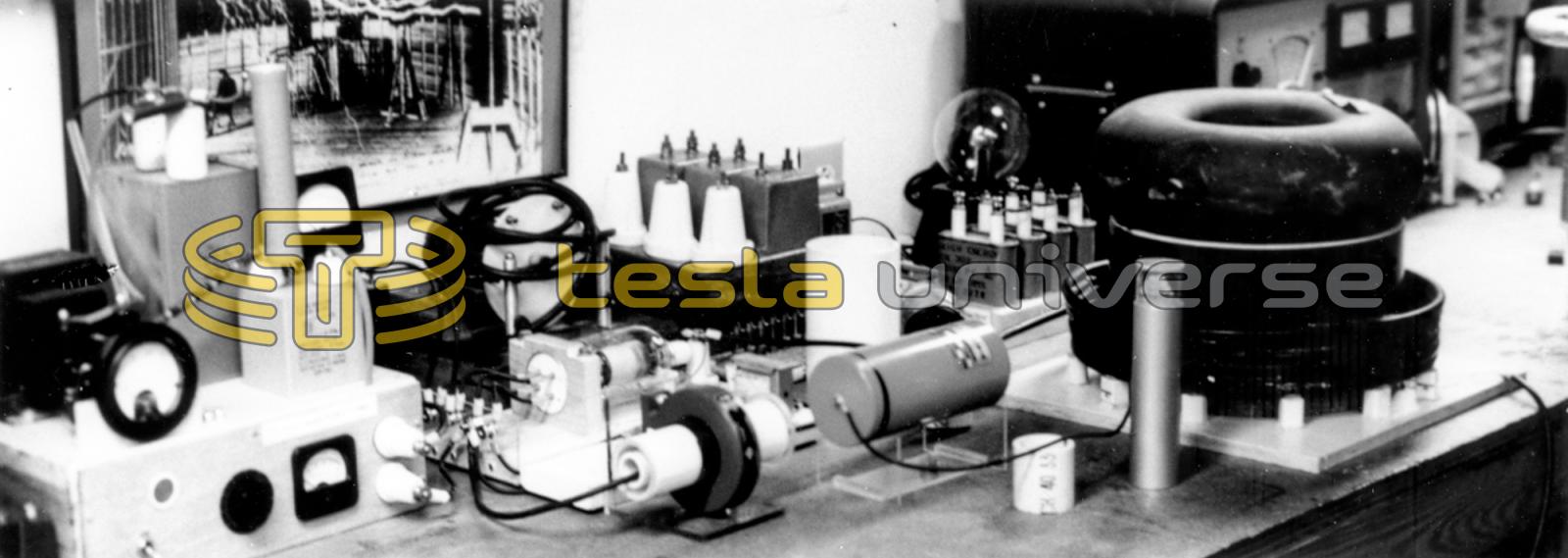
Above: The author's system. Left to right above - HV DC power supply, dark ring and white tube is a wideband current transformer for measuring tank current. H2 Thyratron is laying on side in mount just to the upper left of the C.T. The dark cylinder is the .008 ufd. tank capacitor. The primary and secondary of the magnifier #12 driver is seen extreme right. Drive circuitry and low voltage supplies, not seen, are obscured by C.T. and capacitor.
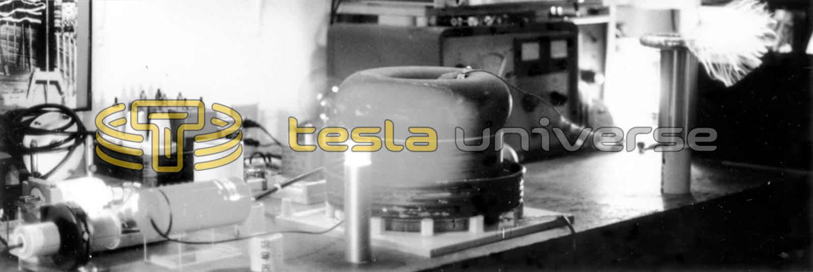
Below: In operation at 70 watts DC input. Resonator shown at right with 6" sparks issuing from toroid. E field is very intense, lighting all fluorescent lamps in vicinity. Firing H2 Thyratron glows at left.