
TCBA Volume 11 - Issue 1
Page 12 of 18
Magnification at Last! - We Hope
In early January our group literally stumbled into our first magnifier system! By assembling existing primary/secondary systems in different combinations we achieved magnification. Our first system is shown in diagram #2. The frequencies of the coils didn't match though and we scratched our heads for a while trying to explain what we had just created. The frequencies of the coils were all wrong! The two seemingly had no match 1/2 wave or 1/4 wave. We had 3 foot sparks out of the little 3" extra coil at only ~1200 watts input and so far as we were concerned this must be magnification. One test for magnification is that there should be a nodal point (low impedance) at the junction of the secondary and base of the extra coil. We added a 12" toroid to the top of the secondary and it was as if we never put it there! We did not have to retune our system at all! Sparks still poured off of the little extra coil. This, we took as a nodal point and therefore one of the critical points of a magnifier seemed as if was achieved. Still, we were perplexed about those frequencies though since we had re-characterized the separate coils over and over again and the numbers stayed the same. We now seemed to have a magnifier working but how did all these frequencies get here!
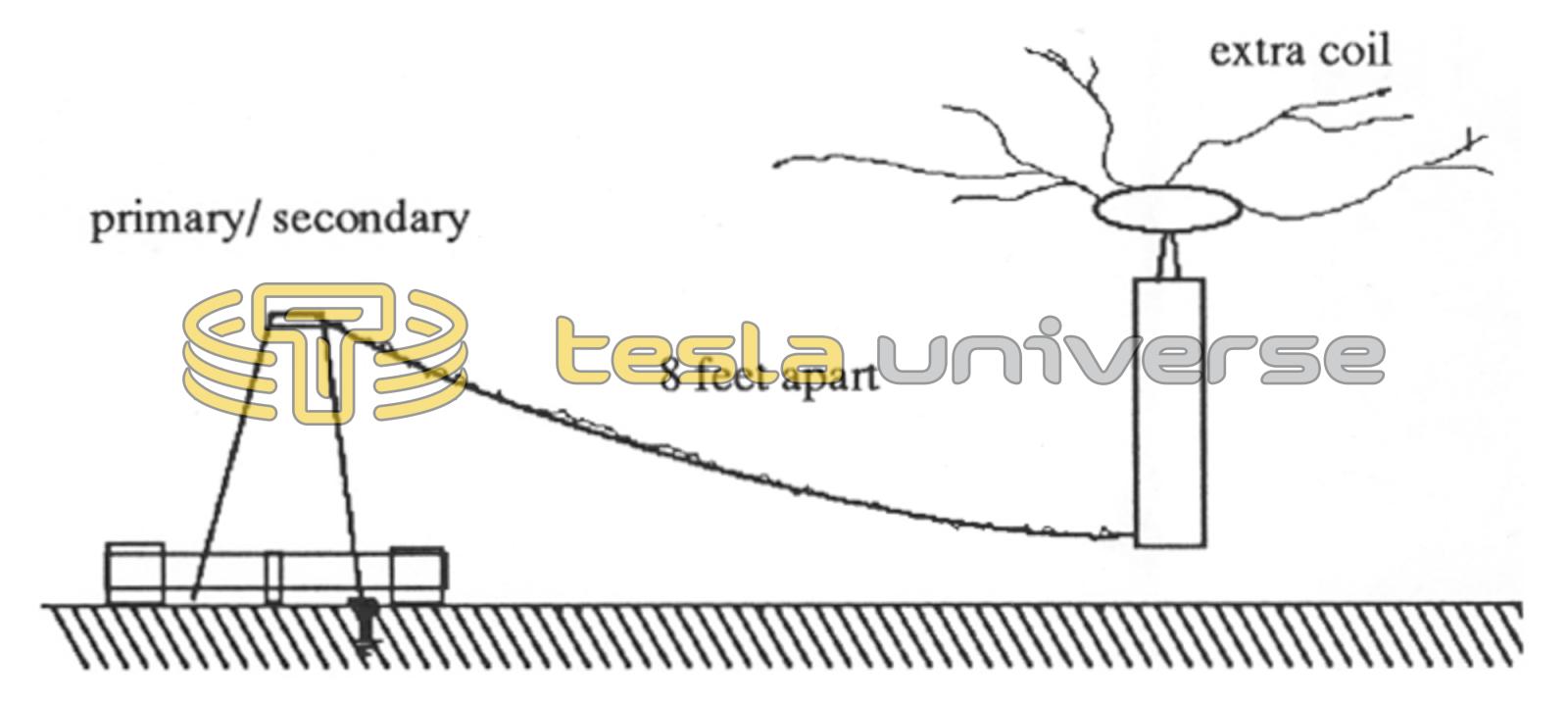
Original Magnifier system used a large banded primary and a cone coil type secondary from a dismantled older coil. The extra coil was also an older 3.25" diameter coil wound with #26 wire (945 feet). The cone coil was wound with #18 wire (600 feet). The system coupling was k=.4 and the coils were separated by at least 8 feet! The input power 700-1400 watts yielded 36-48" sparks.
In our literature search we had come across the work of Kenneth and James Corum and felt it to be the best information to be found on the Magnifier and its operation. We re-studied their papers (see list at end of article) and it was in their 1986 Tesla Symposium paper on the extra coil as a helical resonator and transmission line, that we started to realize that we might be just measuring our frequencies in some wrong manner.
The next step was to build a larger magnifier based on their principles. One of the things that they had mentioned, we had already learned and that was that the extra coil was to be of a higher frequency than desired and tuned or lowered into the exact desired frequency by adding capacitance to the top if it. Next we also verified that a nodal point is located at the connection point on top of the secondary and base of the extra coil. There might be 100,000 volts at this point but it was acting like a super excited R.F. ground point!! We started from scratch, custom winding a secondary and primary just for use as a magnifier. We set up the system as in our final diagram #3 and it has been used for some time in experiments with power levels around 2 KW. We had the same problem again and this time we measured a secondary 1/4 resonance at 250 KHZ but the extra coil was performing best when loaded down to 168 KHZ! After much trial and error the apparent “secret” was found. Since there is a nodal point at the junction of secondary and extra coil we tried to characterize the connected system from this point and found that the two coils dipped almost on top of one another at 168 KHZ!! But shouldn't a coil measure the same resonant frequency whether measured from the top or bottom? In the void of interstellar space of course it will, but on earth sitting on a floor inside a big primary it won't! It seems that looking back from the nodal point the secondary looks as if it is a heavily top (bottom loaded) coil and its resonant frequency drops, so the base measured resonance of 250 khz was wrong since the magnifier's critical nodal point saw it as a capacitvely loaded 250 KHZ coil now operating at 168 KHZ! This is the way we theorise that measurements should be taken in a magnifier. This also points up the fact that the primary secondary system is very sensitive to coupling and position above ground level! Changing the position of the system or moving the mass of the primary about the secondary to alter coupling will change the tune of the system requiring adjustment of the extra coil also. The only thing we saw on coupling was that one should strive to get the tightest coupling possible to transfer as much power to the secondary as possible. There is no need in a small coil to shoot for a K value of .6 or more. At the higher frequency that small coils operate your amateur gap may not be able to give a short enough quench time to allow the energy to be utilized for magnifier action to occur. It is highly recommended that the Corum's work be consulted on this point. The spark gap, it seems, is the big snag in magnifier construction, it must be capable of very rapid breaks. Note that we said rapid breaks, not necessarily a large number of breaks per second. We have found that a two or three point rotary rotating at 8,000 RPM might do a better job of quenching than a 16 point one at the same speed. Ultimately the gap must compliment the coupling and the size capacitance used in the primary circuit