
TCBA Volume 11 - Issue 1
Page 8 of 18
Tesla Coils Resurrected
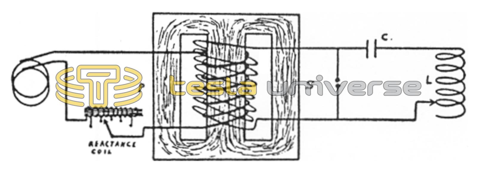
164. In figure 111, a spark gap, having a condenser and inductance coil in series with it, is placed across the secondary of a step-up transformer. This will produce a brilliant discharge across the gap.
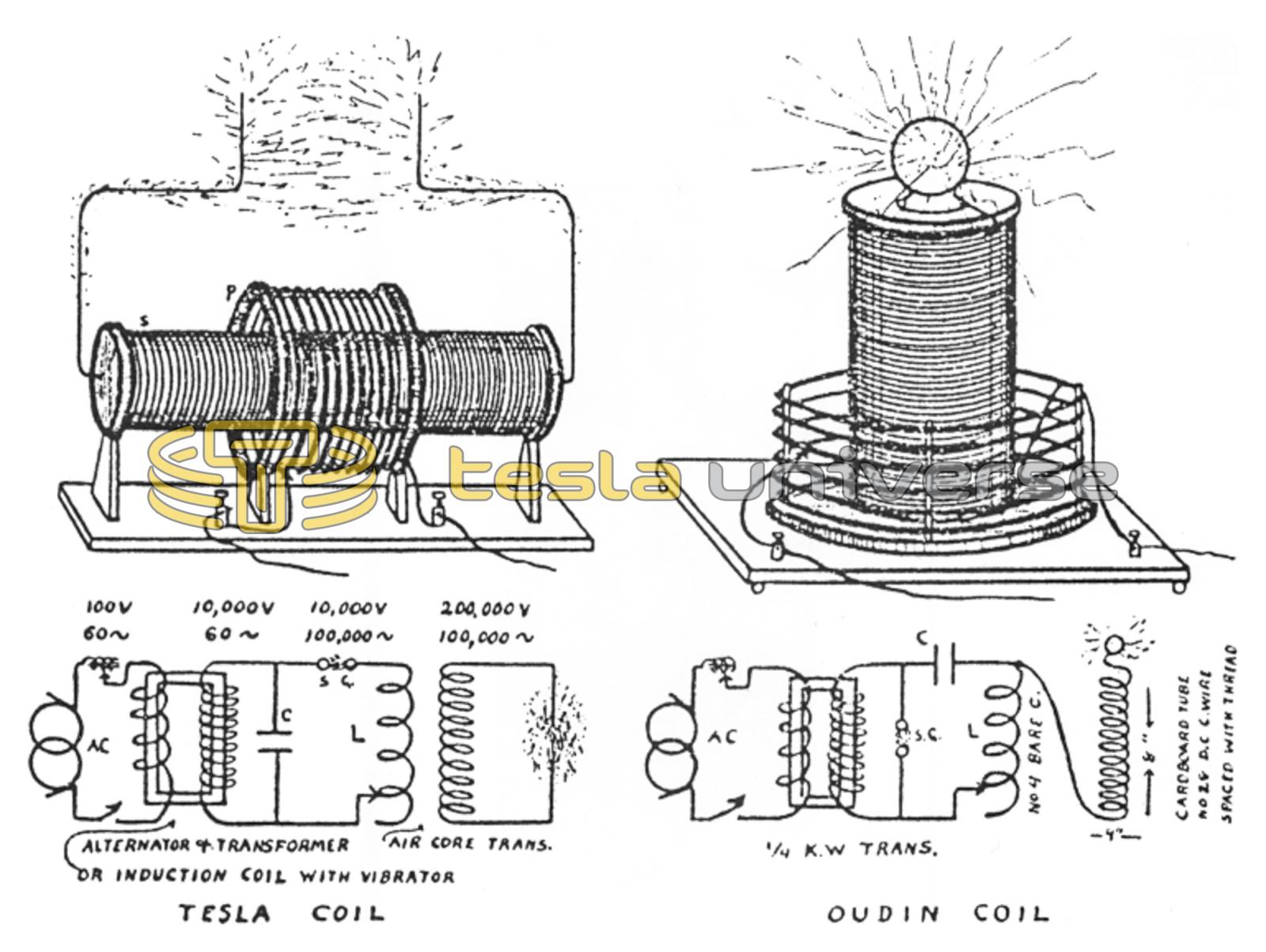
The brilliant spark is due to the extremely high frequency of the current in the condenser circuit. (See chapters 17 and 18.) The famous Tesla coil, figure 112, popular for entertainments and amateur experiments, makes use of practically the same circuit as that illustrated in figure 111. In this a secondary coil of many more turns of wire is inductively coupled to L, and across this is a second spark gap, which may be made to produce a very spectacular electrical display. When the secondary coil is conductively coupled to L, the sparking will take place at the terminal of this coil, a large brass ball being usually arranged at this point to make the greatest display of “fireworks.” This is known as an Oudin coil, or resonator.
The spark can be made to jump several feet from the brass ball to another piece of metal. On account of the extremely high frequency of this discharge, it is not considered dangerous to human life. It is well, however, to make sure that the body of a person handling it is well insulated from the earth.
It is found that by adding an iron core inductance coil, generally called a reactance coil, in series with the primary circuit of the transformer, we can tune the transformer to a period to correspond with the frequency of the alternator; and also, within limitations, we can balance the impedence of both circuits of the transformer. This condition is called resonance, and this arrangement is known as a tuned transformer, or a resonant transformer. The 2 K. W. Spark transmitter, diagram of which is given in chapter 39 is equipped with a reactance regulator. The function of the step-up transformer in this is to provide a high-voltage alternating current for use in charging the condensers, without, the necessity of employing an alternator of the great bulk and costliness which would otherwise be required. The function of the reactance regulator is to vary the power input to the transformer.
(Editor's note: This is one of those rare instances in which a writer appears to have an understanding of the difference between a Tesla and Oudin coil. The diagram at the right shows the bottom turn of the secondary coil brought up to, and connected with, the top turn of the primary. Electrically speaking, it is an Oudin coil. The manner of construction, however, is closer to that of a Tesla coil. This project might well be called a Oudin/Tesla coil. By connecting the bottom turn of the secondary to the bottom turn of the primary, it would become a true Tesla coil.)
RADIO THEORY AND OPERATING by Mary Texana Loomis, Loomis Publishing Co., Washington, DC 1928 (4th ed.)