TCBA Volume 19 - Issue 1
Page 12 of 18
Crowd Stopper II
By
Nick Caimano
“Crowd Stopper II” is a variation on the old repulsion coil principle. Only here, it is a double version. This project is based on the “Crowd Stopper” article in the 1967 (Spring Issue) of Electronic Experimenter's Handbook. Although the electrical circuit is practically identical to the original article, the construction is a bit different.
First of all, I did not build the box but used an old microscope case. Secondly, I did not wind my own field coils but purchased two inductors from B.G. Micro (Col 1006) at $1.95 each. They are able to handle 9+ amperes. The inductors have a small center hole which I enlarged to 1/4" using a carbide drill (do not force as the material is brittle).
Thirdly, I did not make the loop but retrieved a ready-made loop from an old metal planter that was purchased at a flea market. The planter had about a half-dozen loops. The transformer was purchased from Marlin P. Jones & Associates (7846 TR) for $17.99. This is a 110/220 VAC to 24 V (12-0-12), 10 ampere unit. I hooked it up with a half/full-power toggle switch to give a choice of either 12 volts @ 4 amperes or 24 volts @ 8 amperes. Strangely, I could not detect any difference between the two settings so opted for 12 volts @ 4 amperes.
The indicator lamps are Radio Shack “Jumbo Red” (272-336) units at $2.59 per package of two. The 6 rpm motor was purchased from the Surplus Center in Lincoln, NE for $8.95 (5-1217). In retrospect, I would recommend either a 10-12 rpm motor or adding more electrodes on the rotating switch.
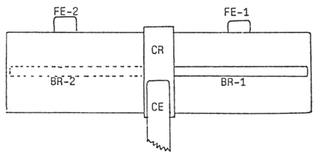
The rotating switch was made from a cylinder purchased at a surplus mart. It is made of some type of insulating material and came complete with a center-drilled hole for the motor shaft and a set screw to anchor it. The only thing I had to do is to cut it down to the desired length. One problem encountered was the occurrence of arcing when the rotating electrode separated from the fixed electrode. Evidently, a back voltage was being produced when the circuit opened. The problem was greatly reduced by connecting the fixed electrodes with capacitors of .1 mfd at 200 volts (Radio Shack 272-1053). The details of the rotating switch are shown below.
- FE-1 & FE-2 are fixed electrodes
- CR is a copper ring (cut from copper pipe)
- CE is the common electrode which rides CR
- BR-1 & BR-2 are 1/8" brass rod rotating electrodes
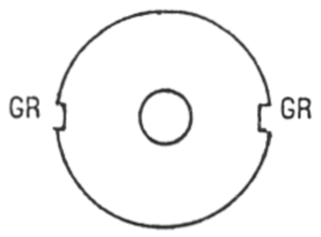
- GR=grooves into which BR-1 and BR-2 are glued. BR-1 & BR-2 are soldered to CR.
The cylinder (rotor) is made of 5/16" ID x 5/8" long aluminum. I couldn't find a suitable aluminum tube so cut the cylinder from the tube of my soap stone-marker (available at hardware stores).


