TCBA Volume 19 - Issue 1
Page 8 of 18
Parts List
- I1, I2 - 12-16 volt miniature bayonet lamp
- L1, L2 - See text
- S1 - S.p.s.t. toggle switch
- S2 - See text
- T1 - Filament transformer; 117-volt primary, 12-16 volt secondary, 2 amp., minimum (Allied Radio 62 G 331 or equivalent)
- 1 - 6-rpm timing motor, 117 volts a.c., 60 cycles - see text
- 1 - 7" x 12" x 3/16" piece of Masonite
- 1 - 2 3/4" x 2 3/4" x 3/16" piece of Masonite
- 1 - 3" x 7" x 12" aluminum chassis (Bud AC-408 or equivalent)
- 1 - 24" soft iron rod, 1/4" diameter
- 2 - 1 3/8" fiber or Micarta washers, 1/8" thick
- 1 - 8' length of soft iron wire, 16 or 18 gauges
- 1 - 22-gauge enameled magnet wire - see text
- 2 - Pilot light assemblies (Allied Radio 7 E 891)
- 1 - 1/2" brass rod, 1/2" diameter
- 4 - Pieces of 20- or 22-gauge round brass tubing, 1/4" o.d., 1/2" long
- 1 - 1/2" piece of 20- or 22-gauge seamless aluminum tubing, 3/8" o.d. (won't work with a seam)
- 4 - 5/16" x 9/16" pieces of 26-gauge spring brass
- 1 - 5/16" x 1 7/8" piece of 26-gauge spring brass
- Misc. - Line cord, 3/4" x 6-32 brass round-head machine screws (4), 2" x 6-32 steel round-head machine screws (2); 6-32 hexagon brass nuts (8), 6-32 hexagon steel nuts (2), rubber screw bumpers (4), 3/8" x 6 sheet metal screws (14), 1/2" x 1 1/2" wood dowels (2), 1/4" rubber grommet, 1/4"-20 hexagon steel nuts (4), 3/4"-diameter steel washers with 1/4" center (2), #6 lock washers (4); and #6 brass washers (4)
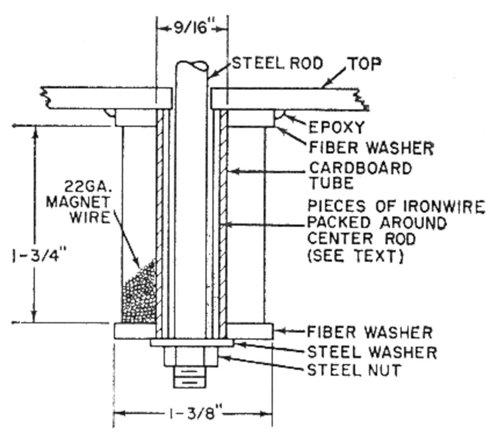
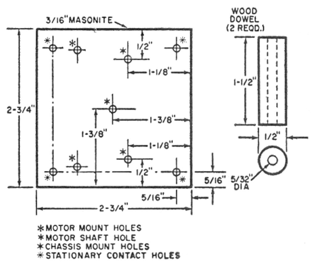
Construction of L1 and L2. Make two coil forms with fiber or Micarta washers and strips of thin cardboard as shown in Fig. 4. Wrap a strip of 2"-wide cardboard around a 1/2" wood dowel and apply glue between the layers of cardboard without getting any glue on the wood dowel. Drill holes in the fiber coil ends to fit the cardboard tube and cement the tube and the ends together. Then drill two 1/16" holes in one end washer of each coil form to pass the wires through.
Wind approximately 80' of No. 22 enamel-covered magnet wire on each form. The exact amount is not important, but it is important to wind the coil turns close together and evenly. Suppliers of magnet wire generally sell the wire wound on 1/2-lb. spools. One such spool is usually enough for both coils.
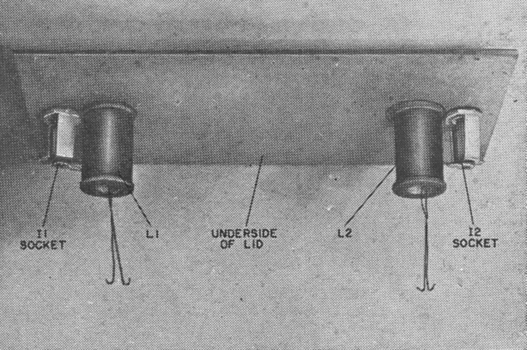
Mount the pilot light assemblies to the Masonite as shown in Fig. 5. Then center the two coils on the underside of the panel and over the 1/4" holes, and cement the coils in place. The aluminum ring which flips back and forth on the steel loop is made from 1/2"-long, 3/8"-o.d., 20- or 22-gauge aluminum tubing; both ends of the ring should be reamed before the ring is placed on the loop.


