TCBA Volume 19 - Issue 1
Page 5 of 18
Input - Output
Q. In regard to your statement (Input-Output, Volume 18, #4), “Incidentally, I don't think a tight coupling would work well with a vacuum tube oscillator unless a suitable pulse width could be attained....” I have run a regular tube TC at very tight coupling of K.3 with very good results.
A. Not having used such a tight coupling with my vacuum tube Tesla coil, I can't speak from experience. And not knowing the other parameters within your coil system makes it even more difficult to respond. If you have had good results using a coefficient of coupling of .3, then all I can say is nice going.
Generally, the literature explaining all of this becomes more than a bit complicated. It involves inductively coupled circuits tuned to the same frequency, coupled circuits tuned to slightly different frequencies (detuning), effective Qs versus actual Qs, Actual coupling versus Critical coupling and so on. I'll leave it to those more knowledgeable on this topic to take up the flag. Anyway, I did qualify my reply by confessing a limited understanding of the complexities of TC circuits.
Q. I've heard of coefficient of coupling and critical coupling but always considered them to be one and the same. Apparently, they are two different and separate quantities.
A. Coefficient of Coupling (K) is set by the physical position of the primary inductor relative to that of the secondary inductor. Unless you build a means for varying the distances between the two coils or the angles of one to the other, K remains fixed.
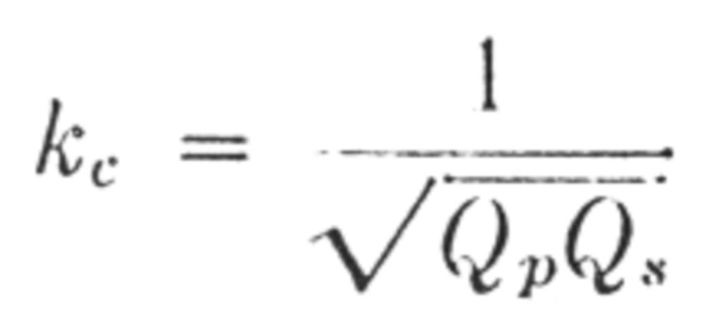
Critical Coupling (Kc) is dependent primarily on the Qs of the primary and secondary circuits. Maximum output is achieved at Critical Coupling.
The Qs of a circuit can vary in regards to what's going on in the circuit. Therefore as Qs vary, so does the Critical Coupling. As stated in the above reply, Effective Q versus Actual Q and Actual Coupling versus Critical Coupling must be addressed. And it gets even more complicated than this.
In Volume 18, #4, I gave an example of a transmitter getting a maximum peak (highest voltage) when set at a K of .26. Since maximum output occurs at Kc, I wondered whether K and Kc were not one and the same.
Q. In regard to your “Did You Notice” comment (Tesla's 1897 lecture), I noticed a circuit Tesla used for a double-ended system with the capacitor across the transformer secondary and a spark gap on each leg.
A. Readers can see this circuit on page 14 of Leland Anderson's book covering Tesla's lecture (21st Century Books). On page 14, a circuit is shown of a double-ended coil with the primary/secondary turns ratio of 1:1. It was then asked, how is it possible to obtain a voltage rise under those conditions. Anderson points out that high Q values and properly adjusted lengths of the primary and secondary coils were necessary. Take note that the length of the wire in the primary is the same as the length of the wire in the secondary. Strange, indeed.
Incidentally, did you notice that Tesla used choke coils on each leg of the high voltage transformer?

