TCBA Volume 19 - Issue 1
Page 7 of 18
This Amazing Ring Hops from One Side to Another, Chasing the Flashing Lamps
By Walter B. Ford
Build the
Crowd Stopper
The timing motor operates directly off the 117-volt line. Coils L1 and L2 operate off the 12-volt secondary winding of T1. Lamp I1 is wired across L2 and lights when this coil is energized. Similarly, lamp I2 is connected across L1 and lights when L1 is energized. Because each lamp is physically located opposite its coil, there is the illusion that the lamp attracts the ring.
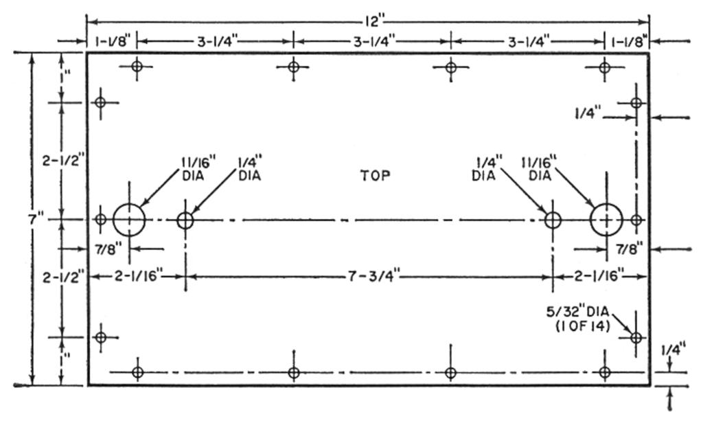
Construction. Drill the Masonite panel as shown in Fig. 2. Place the drilled panel over the open space on the aluminum chassis; then mark and drill around the flanged edges of the chassis as shown. Drill a few additional holes in the chassis for ventilation, line cord entrance, switch mounting, and rubber feet.
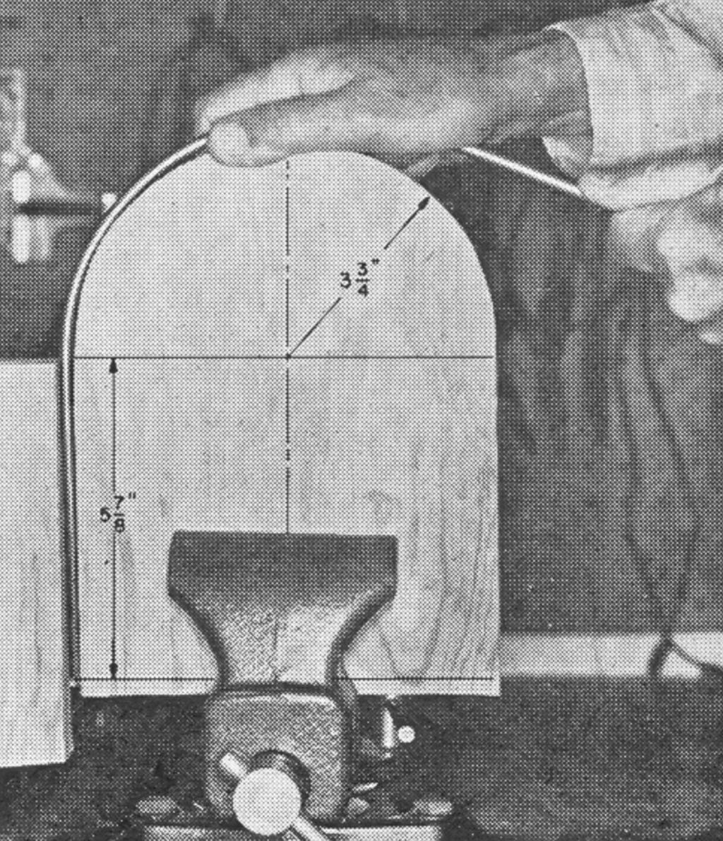
Remove any nicks from the 24" soft iron rod being used for the loop, with a fine file or sandpaper. Then polish the rod with emery cloth and steel wool. Make a wood form for shaping the loop (Fig. 3). Attach another piece of wood to the form by means of a back plate so as to provide a slot for holding one end of the rod.
Place the form and back plate in a vise, and insert the iron rod into the slot so that the end of the rod is positioned 5 7/8" from where the semicircle ends. Bend the steel rod around the form, using a rubber mallet or block of wood as necessary. If one side of the rod is longer than the other after forming, cut it to make both sides even. Then thread about 1/2" from the ends using a 1/4" die.


