
TCBA Volume 19 - Issue 1
Page 9 of 18
Insert the ends of the loop from the top of the panel through the centers of the coils until the ends extend 1/4" beyond the coils. Then turn the unit upside down and support the ends in the same position. Cut a number of pieces of No. 16 or 18 soft iron wire, each slightly less than 2" long, and straighten the pieces as much as possible. Then insert the wires around the steel loop ends (Fig. 4) in the center of the coils, applying a coating of epoxy cement to each piece as it is inserted in place.
Tightly pack both coils with the wires. You'll find it easier to insert the wires if you sharpen one end of the wire with a file. Then cut notches in the steel washer to clear the coil leads; place the washers and nuts over the 1/4" rod projecting from the coil ends. Do not tighten the nuts until the epoxy glue has set.
Drill the 2 3/4" x 2 3/4" Masonite board used to mount switch S2 as shown in Fig. 6. Measure the spacing of the mounting holes on your timing motor and drill corresponding holes in the base.
Herbach and Rademan Inc., 1204 Arch St., Philadelphia, Pa., 19107, offers a line of synchronous timing motors from 1/2 to 30 rpm. The 6-rpm model is priced at $4.95, f.o.b. Philadelphia. Motor rpm is not critical and almost any timing motor, down to 1 rpm, will work well.
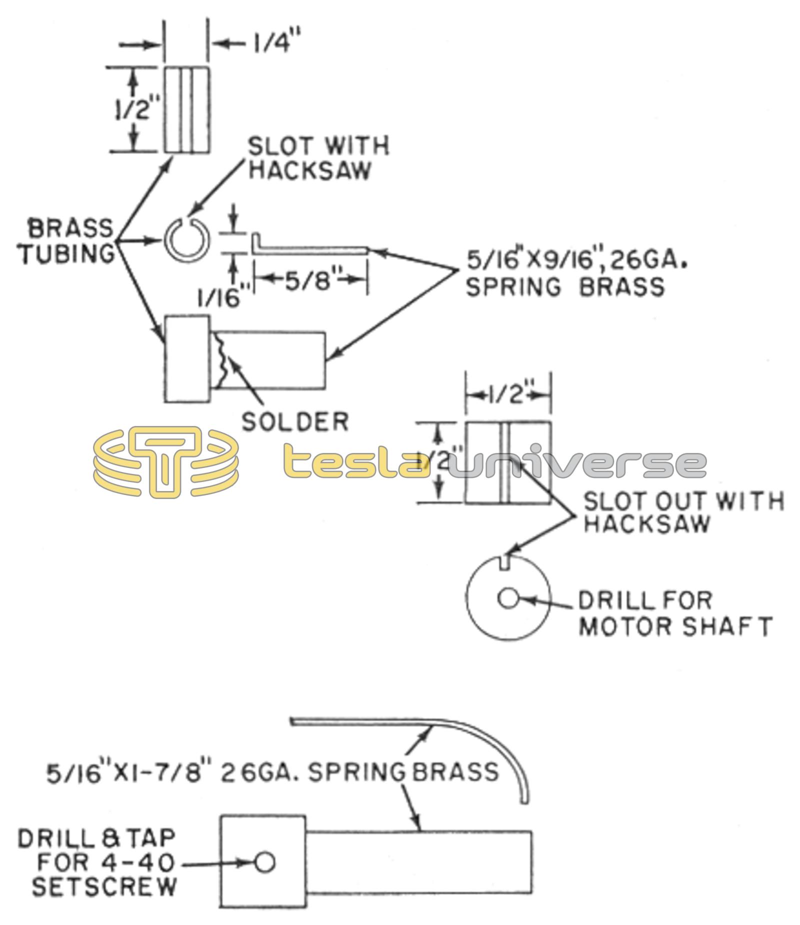
Next, start making the four stationary contacts from 20- to 22-gauge, 1/4"-o.d., brass tubing cut to 1/2" in length. As shown in Figs. 7, 8, and 9, they are made by soldering a 5/16" x 9/16" 26-gauge piece of brass spring into the slotted tubing. When making the contacts, cut each length in line with the “grain” of the metal to prevent it from snapping when bent. The alignment of the grain can be determined by observing the direction in which the metal tends to curl when laid on a flat surface.
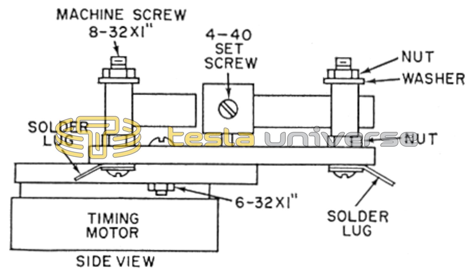
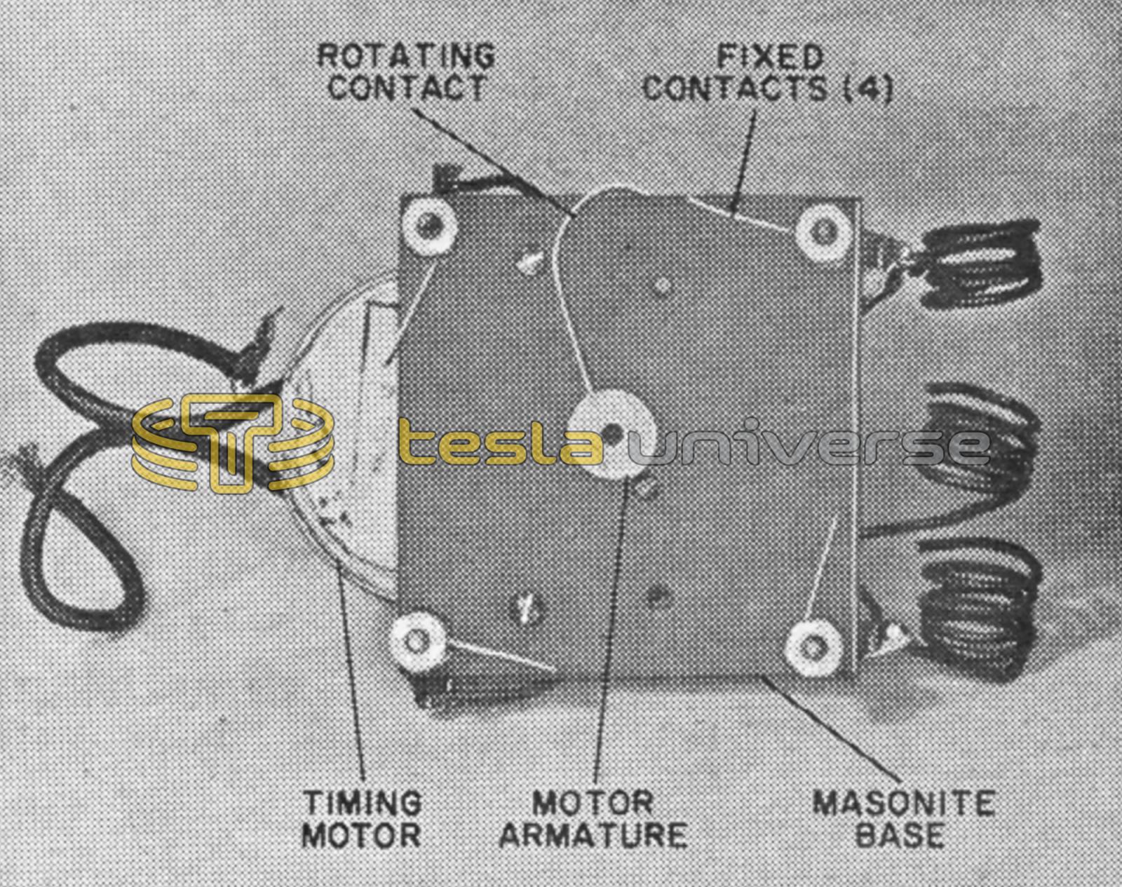
The rotating contact is made by soldering a strip of spring brass into a piece of slotted brass rod as shown in Fig. 7. Dress down the edges of the rotary and stationary contacts to insure quiet operation. Each of the four stationary contacts is mounted on a 3/4" x 6-32 brass machine screw, and the rotating contact is mounted on the armature of the motor.