TCBA Volume 19 - Issue 1
Page 15 of 18
The “Tesla” Effects.
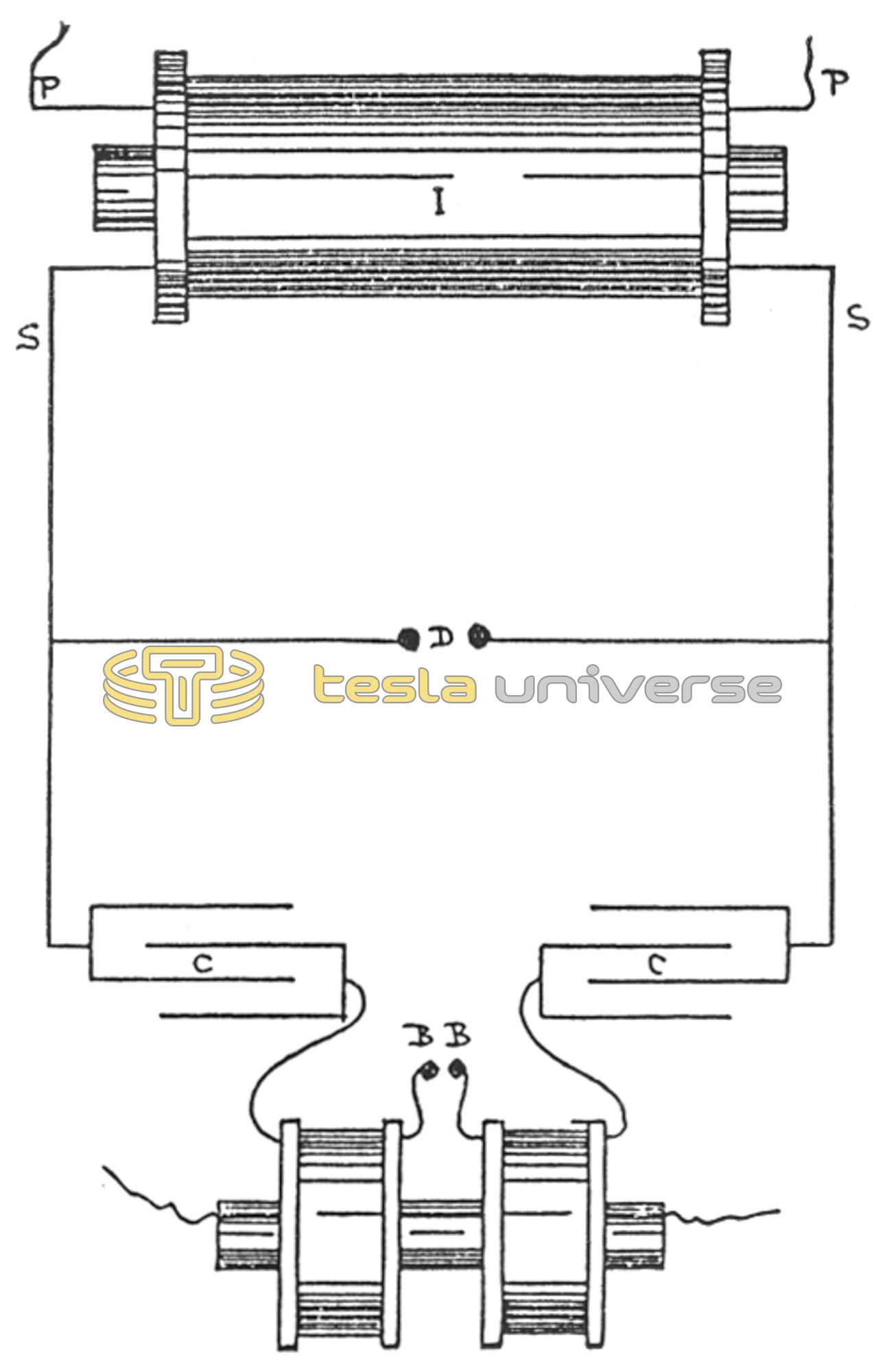
In exploring the comparatively new field opened up by Professor Crookes, Nikola Tesla has stimulated research into the mysteries of high tension and frequency currents and their effects. In the majority of his experiments Tesla uses alternating currents generated by machinery of his own design, but in a large number of cases his effects can be duplicated with an induction coil suitably energized. In the latter case the apparatus consists of a battery, a Ruhmkorff coil, two condensers, and a second specially constructed induction or disruptive coil, with some few subsidiary implements. The contact-breaker or rheotome must be one giving interruptions of very rapid sequence.
Fig. 69 shows a diagram of the Tesla arrangement with a Ruhmkorff coil. The terminals of the secondary coil of the Ruhmkorff coil I terminate at the condensers C C. Bridged across the wires before they reach the condensers is the discharger D. The second terminals of the condensers are led through the split primary of the disruptive coil, terminating at the points B B of the second discharger. The secondary of the disruptive coil is either outside or inside the primary coil. The condensers are of special design, being small, but of high insulation. They each consist of two plates of metal a few inches square immersed in oil and arranged so they can be brought nearer together or further apart, as necessary. Within limits, the smaller these plates are the more frequent will be the oscillations of their discharge. They also fulfill another purpose, they help nullify the high self-induction of the secondary coil by adding capacity to it.
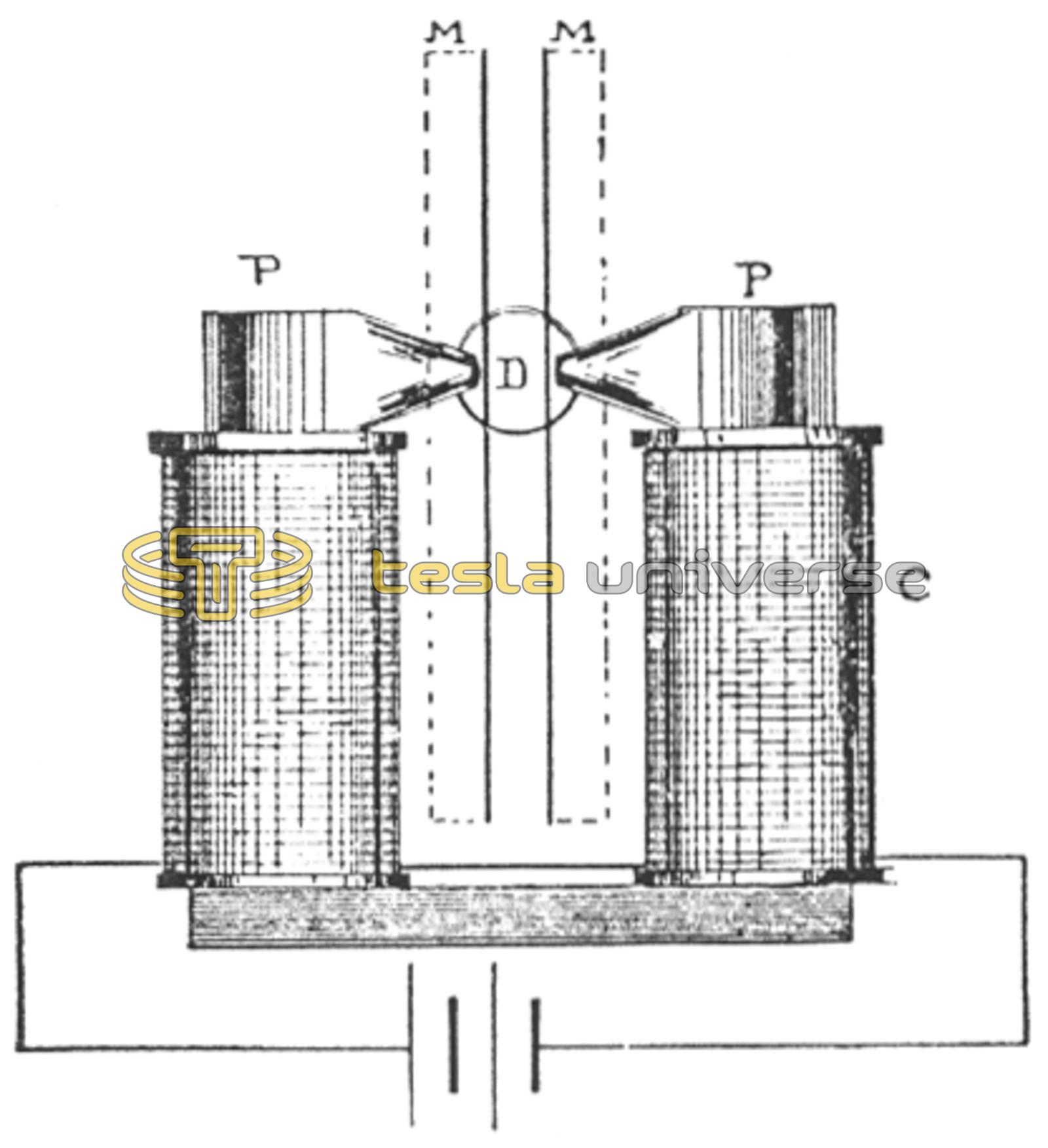
The discharger tips are preferably metal balls under 1 inch in diameter. Tesla uses various forms of dischargers, but for experimental purposes the two metal balls will answer. They are adjusted when the whole apparatus is working according to the results desired. The mica plates serve to establish an air current up through the gap, making the discharge more abrupt, an air blast being also used at times for the furtherance of this object. The device (Fig. 70) consists of an electro-magnet, C, set with its poles P across the air gap, helping to wipe out the spark, as in a well-known form of lightning arrester. This form, described by Tesla, has the pole pieces P shielded by mica plates M, to prevent the sparks jumping into the magnets. Fig. 70 is an elevation and Fig. 71 a plan of this device.