TCBA Volume 19 - Issue 1
Page 14 of 18
Tesla Coils Resurrected
(Induction Coils, How to Make, Use, and Repair Them)
(H.S. Norrie)
(Spon & Chamberlain, NY)
(1901)
Disruptive “Tesla” Coil.
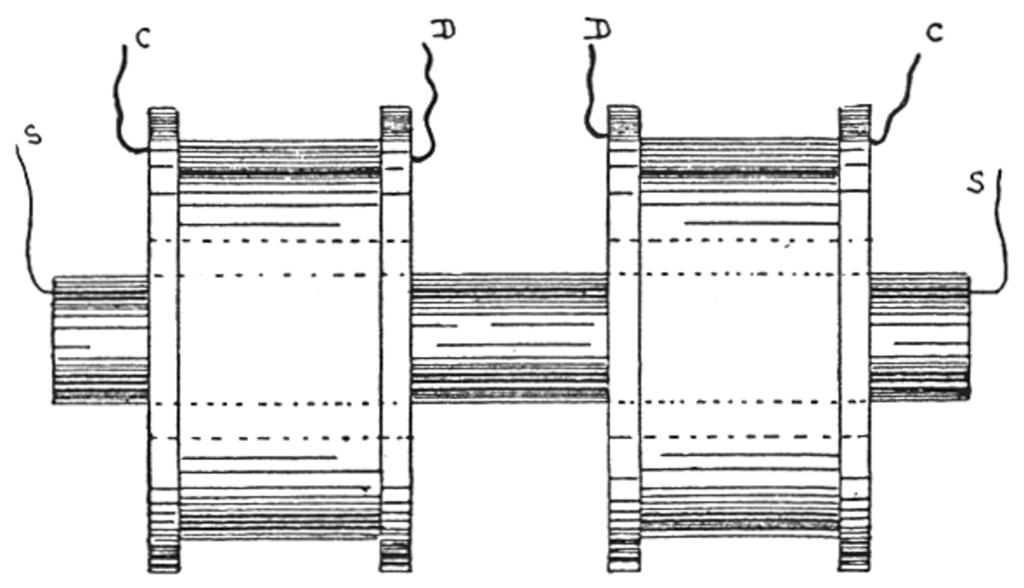
For Fig. 11 the specification is as follows: Secondary, 300 turns of No. 30 B & S silk-covered magnet wire, wound on rubber tube or rod, and the ends encased in glass or rubber tubes. This is inserted into the primary, which consists of two coils, each of 20 turns No. 16 B & S rubber-covered wire, wound separately on a long rubber tube not less than 1/8 inch thick. The last tube must be large enough to be very loose when the secondary coil is inserted in it, and it must project at least two inches over each end of the secondary. A hard rubber division must be placed between these primary coils. The four ends of the latter coils are connected C C to two condensers and D D to two discharger balls, the secondary wires going to the exhibitive apparatus. A further description of these connections is to be found in Chapter XII., also notes upon the use of the disruptive coil.

